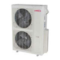
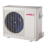
14ACX/XC14 CHARGING INFORMATION
FOR COMPLETE CHARGING DETAILS, REFER TO THE INSTALLATION AND SERVICE PROCEDURES MANUAL (Corp. 0638-L10) AVAILABLE ON DAVENET.
Capacity
-
-
-
-
-
-
-
7 -
-
5
-
Table 13- Normal Operating Pressures
1
°F(°C)
2
TXV System - Liquid Line ( + 10 psig) / Suction Line ( + 5 psig)
65 (18) 228 / 133 232 / 137 224 / 137 235 / 138 233 / 142 231 / 140 233 / 139 238 / 136 239 / 133 239 / 133
75 (24) 264 / 135 265 / 141 260 / 140 274 / 140 256 / 143 269 / 142 272 / 141 277 / 139 278 / 136 278 / 136
85 (29) 311 / 144 308 / 143 304 / 142 319 / 142 299 / 145 312 / 144 315 / 142 320 / 139 323 / 138 323 / 138
95 (35) 360 / 147 357 / 145 353 / 145 367 / 144 343 / 146 360 / 145 361 / 144 369 / 141 370 / 140 370 / 140
105 (41) 414 / 148 407 / 147 405 / 147 420 / 147 389 / 148 414 / 148 413 / 145 422 / 144 415 / 143 415 / 143
115 (45) 472 / 151 463 / 150 461 / 150 478 / 149 452 / 151 471 / 150 465 / 148 481 / 148 476 / 147 476 / 147
°F(°C)
2
RFC System - Liquid Line ( + 10 psig) / Suction Line ( + 5 psig )
65 (18) 234 / 134 235 / 129 229 / 131 237 / 132 228 / 131 230 / 134 232 / 125 240 / 126 244 / 125 244 / 125
75 (24) 268 / 138 268 / 135 268 / 137 275 / 137 263 / 138 267 / 139 268 / 133 281 / 133 281 / 131 281 / 131
85 (29) 310 / 143 309 / 140 310 / 141 319 / 141 306 / 144 308 / 145 312 / 140 324 / 138 324 / 136 324 / 136
95 (35) 356 / 147 356 / 145 351 / 145 364 / 145 348 / 148 354 / 149 357 / 144 371 / 142 370 / 141 370 / 141
105 (41) 407 / 151 405 / 148 402 / 149 415 / 149 395 / 151 406 / 153 406 / 149 420 / 146 418 / 145 418 / 145
115 (46) 462 / 155 463 / 153 458 / 153 472 / 152 453 / 155 459 / 156 460 / 152 473 / 150 471 / 147 471 / 147
Table 14- Approach (APP) Values
3
-TXV System - ºF (ºC) + 1ºF (0.5ºC)
65 (18) 5 (2.8) 4 (2.2) 4 (2.2) 7 (3.9) 3 (1.7) 6 (3.3) 9 (5.0) 7 (3.9) 8 (4.4) 8 (4.4)
75 (24) 6 (3.3) 7 (3.9) 6 (3.3) 8 (4.4) 3 (1.7) 5 (2.8) 9 (5.0) 8 (4.4) 9 (5.0) 9 (5.0)
85 (29) 6 (3.3) 7 (3.9) 6 (3.3) 8 (4.4) 4 (2.2) 5 (2.8) 8 (4.4) 8 (4.4) 9 (5.0) 9 (5.0)
95 (35) 6 (3.3) 6 (3.3) 6 (3.3) 7 (3.9) 4 (2.2) 5 (2.8) 8 (4.4) 8 (4.4) 9 (5.0) 9 (5.0)
105 (41) 4 (2.2) 5 (2.8) 8 (4.4) 7 (3.9) 4 (2.2) 5 (2.8) 8 (4.4) 8 (4.4) 9 (5.0) 9 (5.0)
115 (45) 4 (2.2) 5 (2.8) 5 (2.8) 6 (3.3) 5 (2.8) 4 (2.2) 8 (4.4) 9 (5.0) 9 (5.0) 9 (5.0)
Table 15- Subcooling (SC) Values
4
-TXV System - ºF (ºC) + 1ºF (0.5ºC)
65 (18) 8 (4.4) 10 (5.6) 8 (4.4) 8 (4.4) 9 (5.0) 8 (4.4) 6 (3.3) 8 (4.4) 6 (3.3) 8 (4.4)
75 (24) 7 (3.9) 6 (3.3) 6 (3.3) 7 (3.9) 7 (3.9) 8 (4.4) 6 (3.3) 8 (4.4) 5 (2.8) 7 (3.9)
85 (29) 8 (4.4) 7 (3.9) 6 (3.3) 8 (4.4) 7 (3.9) 9 (5.0) 6 (3.3) 8 (4.4) 5 (2.8) 8 (4.4)
95 (35) 8 (4.4) 8 (4.4) 7 (3.9) 8 (4.4) 7 (3.9) 9 (5.0) 6 (3.3) 8 (4.4) 4 (2.2 7 (3.9)
105 (41) 10 (5.6) 8 (4.4) 7 (3.9) 9 (5.0) 7 (3.9) 10 (5.6) 6 (3.3) 8 (4.4) 4 (2.2) 6 (3.3)
115 (46) 11 (6.1) 8 (4.4) 7 (3.9) 9 (5.0) 6 (3.3) 10 (5.6) 5 (2.8) 7 (3.9) 3 (1.7) 6 (3.3)
1
Typical pressures; indoor evaporator match-up, indoor air quantity and
evaporator load will cause the pressures to vary.
2
Temperature of air entering outside coil.
3
Approach = Liquid Line Temperature minus Outdoor Ambient Temperature
4
Subcooling = Saturation Temperature minus Liquid Line Temperature
AIRFLOW CHECK - Both airflow and refrigerant charge must be monitored for a
proper system set‐up. It may be necessary to alternately check and adjust the
airflow and the refrigerant charge.
NOTE: Be sure that filters and indoor and outdoor coils are clean before testing.
To determine temperature drop across indoor coil (Delta-T), measure the entering
air dry bulb (DB) and wet bulb (WB) temperatures at the indoor coil. Find Delta-T
in table 16. Measure coil's leaving air DB and subtract that value from entering air
DB. The measured difference should be within +
3ºF (+1.8ºC) of table value; if too
low, decrease the indoor fan speed (refer to indoor unit for information). If the
Delta-T is too high, increase the indoor fan speed. Repeat charging procedure and
Delta-T (air flow adjustment) procedure until both are correct.
Example: assume entering air DB - 72, WB - 64, leaving DB - 53. Therefore, Delta-T
should be 15 (per table); delta across coil is 72 - 53 or 19 (which is 4ºF higher than
table value); action necessary: increase fan speed.
Table 16. Evaporator Coil Delta-T
Dry bulb 80 24 24 24 23 23 22 22 22 20 19 18 17 16 15
temperature 78 23 23 23 22 22 21 21 20 19 18 17 16 15 14
of air 76 22 22 22 21 21 20 19 19 18 17 16 15 14 13
entering 74 21 21 21 20 19 19 18 17 16 16 15 14 13 12
indoor 72 20 20 19 18 17 17 16 15 15 14 13 12 11 10
coil (ºF) 70 19 19 18 18 17 17 16 15 15 14 13 12 11 10
ºF 57 58 59 60 61 62 63 64 65 66 67 68 69 70
[ Wet bulb temperature of air entering indoor coil ]
Table 17. RFC Sizes
Capacity -018 -024 -030 -036 -041 -042 -047 -048 -059 -060
RFC Size 0.053 0.060 0.067 0.071 TXV 0.083 TXV 0.083 TXV 0.093
Table 18. Superheat Value (RFC)* + 1ºF (0.5ºC)
Outdoor Temp (ºF)
65 70 75 80 85 90 95 100 105
C
A
P
A
C
I
T
Y
-018 21 21 21 20 19 18 16 13 10
-024 24 23 22 21 20 18 15 13 9
-030 22 20 19 17 15 13 12 10 6
-036 21 20 19 17 15 13 10 8 5
-042 23 22 20 18 15 12 8 4 2
-048 35 30 25 22 18 12 8 5 5
-060 35 30 25 22 18 12 8 5 5
*Suction line saturation temperature minus suction line temperature. All measurements are at the service valves and are based on 80db / 67wb indoor temperature.

 Loading...
