Page 13
Troubleshooting
The EGC control board is equipped with two diagnostic green
LEDs to indicate the mode of failure. The LED lights are
marked DIAG #1 and DIAG #2. The codes are given in table
4. On the EGC−1 only, the last failure code is stored in
memory and may be retrieved by depressing and holding
the memory recall button. When this button is depressed,
the LEDs will signal the last failure code in memory. Power
must be restored to the control (depress blower interlock
switch) within one minute of blower access panel removal in
order to retain memory. To clear the memory of the stored
failure code, remove main power and short the jumper next
to the diagnostic button for five seconds.
TABLE 4
EGC DIAGNOSTIC CODES
DIAG #2 DIAG #1 DIagnostic Condition
Simultaneous
Flash
Simultaneous
Flash
Power ON". Normal Operation. In-
creased flash rate indicates there
is a heating demand.
On Flash
Primary or Secondary
Limit Switch Open.
Auto-Reset Switch.
Flash Off
Pressure Switch Watchguard,
pressure switch opened during
operation or condensate
drain blocked.
Alternate
Flash
Alternate Flash
Watchguard, burners
failed to ignite.
Off Flash
Flame sensed without
valve energized.
Flash On
Roll-out Switch Open.
Manual-Reset Switch.
Continuous
On
Continuous On
Circuit board self-check failure or
ignition/blower control
is wired incorrectly.
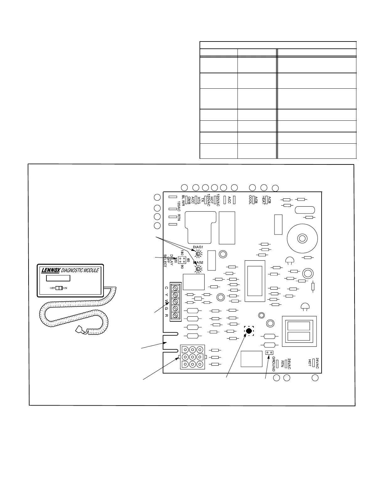
FIGURE 8
EDGE
CONNECTION
THERMOSTAT
TERMINAL STRIP
(DETACHABLE)
BLOWER TIME
ADJUSTMENT
JUMPER
DIAGNOSTIC MODULE
DIAGNOSTIC LEDS
RED DIAGNOSTIC BUTTON
(EGC−1 only. Depress button and hold
for display of last failure code.)
DIAGNOSTIC CODE ERASE JUMPER
(Remove power to control and short pins for
10 seconds to erase previous code.)
24VAC
PLUG P20
5
6
7
8 9 10 11 12 13 15
123
4
14
16
1
2
3
4
6
5
7
8
9
EGC−2 INTEGRATED CON-
TROL
NOTE: EGC−1 board will have terminal (#15) for
ACB low speed.
*
*
**
**
NOTE: EGC−1 board will have terminal
(#16) for ACB Heat speed.
 Loading...


