Page 14
TABLE 5
BLOWER CONTROL A15 TERMINAL DESIGNATIONS
Terminal
Designation
(See fig. 8)
Type Function
R Screw Strip 24VAC to Thermostat (Red)
G Screw Strip
Manual Fan Input from Thermostat
(Green)
W Screw Strip
Heat Demand Input from Thermostat
(White)
Y Screw Strip
Cool Demand Input from Thermostat
(Yellow)
C Screw Strip Common Ground to Thermostat
1 1/4" Spade 24VAC Hot from Transformer
2 1/4" Spade 24VAC Return to Transformer
3 1/4" Spade 24VAC Ground
4, 5, 6 1/4" Spade 120VAC Return − 120VAC Common
7 1/4" Spade
120VAC Return − 120VAC Common
Input
8 1/4" Spade Combustion Blower (Line Voltage)
9 1/4" Spade Heat Only Accessory (Line Voltage)
10 1/4" Spade 120VAC Hot to Transformer
11 1/4" Spade 120VAC Hot Input
12, 13 1/4" Spade Accessories (Line Voltage)
14 1/4" Spade ACB Cool Speed (Line Voltage)
15 1/4" Spade
EGC−1 ACB Low Cont. Speed
(Line Voltage)
EGC−2 ACB Heat Speed
(Line Voltage)
16 1/4" Spade ACB Heat Speed (Line Voltage)
TABLE 6
EGC CONTROL JACK/PLUG 20 TERMINAL DESIGNATIONS
Pin # Function
1 Rollout Switch Out
2 Spare
3 Gas Valve Common
4 Pressure Switch Return
5 Hi Limit Return / Pressure Switch Out
6 Flame Sensor
7 Gas Valve Out
8 High Limit Out
9 Rollout Switch Return
DANGER
Shock hazard.
Disconnect power before servicing. Control is not
field repairable. If control is inoperable, simply
replace entire control.
Can cause injury or death. Unsafe operation will
result if repair is attempted.
5−Flame Sensor (−11 models)
A flame sensor is located on the left side of the burner sup-
port. See figure 9. The sensor is mounted on a bracket in
the burner support and the tip protrudes into the flame en-
velope of the left−most burner. The sensor is fastened to
burner supports and can be removed for service without
removing any part of the burners. During operation, flame
is sensed by current passed through the flame and sens-
ing electrode. The SureLight control allows the gas valve
to remain open as long as flame signal is sensed.
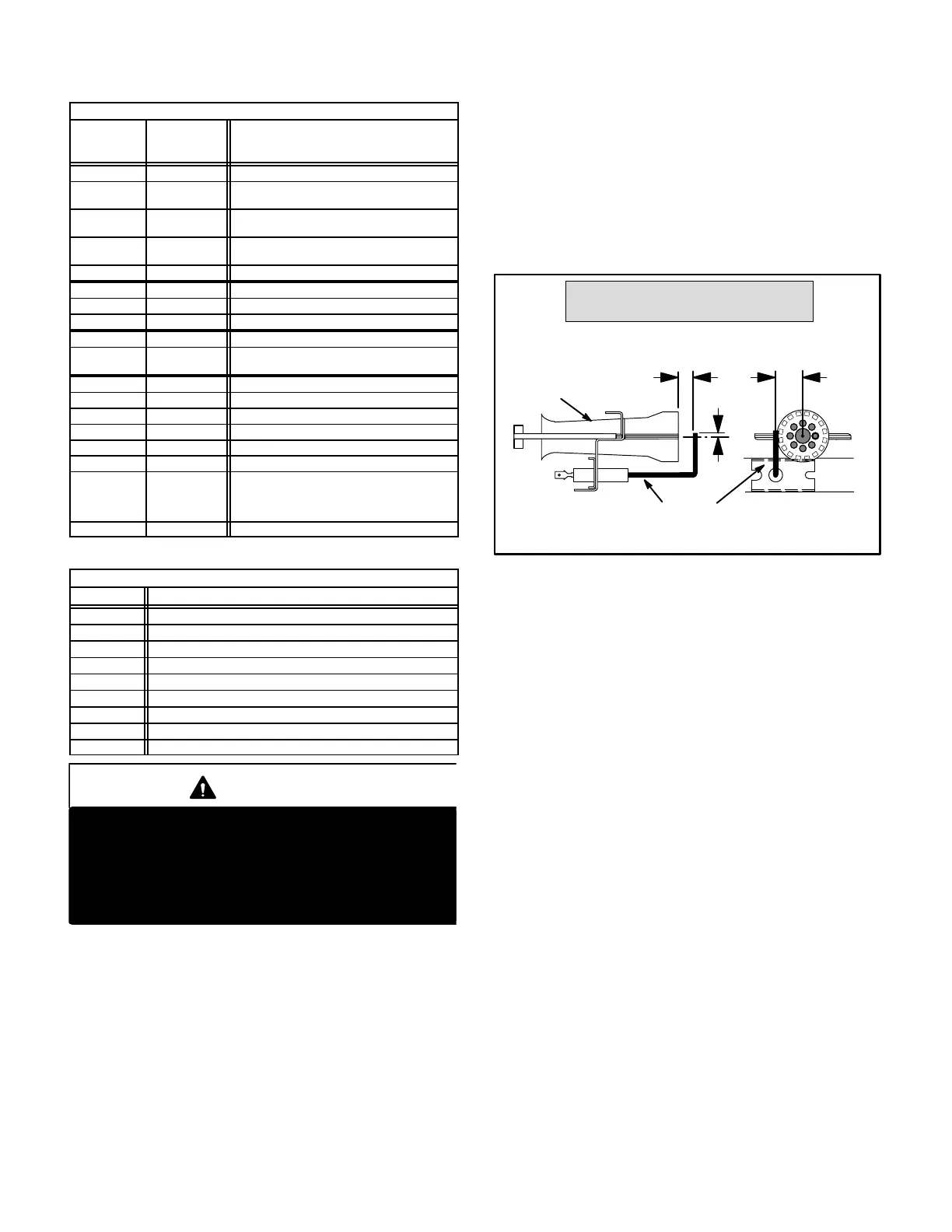
FIGURE 9
NORMAL FLAME SIGNAL u 0.7 MICROAMPS
LOW FLAME SIGNAL v 0.7 MICROAMPS
MINIMUM FLAME SIGNAL v 0.15 MICROAMPS
BURNER
FLAME
SENSOR
SIDE VIEW END VIEW
1/4 in. 7 mm
1/32 in. 0.79
mm
3/16 in.
4.7 mm
11/16 in. 18 mm
1/32 in. 0.79
mm
NOTE − The 80MGF furnace contains electronic com-
ponents that are polarity sensitive. Make sure that the
furnace is wired correctly and is properly grounded.
6− SureLight Ignition System A3
(−11 models)
All 80MGF−11 model units are equipped with the Lennox
SureLight ignition system. The system consists of ignition
control board (figure 11 with control terminal designa-
tions in table 10) and ignitor (figure 12). The board and ig-
nitor work in combination to ensure furnace ignition and
ignitor durability. The SureLight integrated board controls
all major furnace operations. The board also features two
LED lights for troubleshooting and two accessory termi-
nals rated at (4) four amps. See table 9 for troubleshoot-
ing diagnostic codes. Table 7 and 8 show jack plug termi-
nal designations. Units equipped with the SureLight
board can be used with either electronic or electro−me-
chanical thermostats without modification. The SureLight
ignitor is made of durable silicon−nitride. Ignitor longevity
is also enhanced by voltage ramping by the control board.
The board finds the lowest ignitor temperature which will
successfully light the burner, thus increasing the life of the
ignitor.

 Loading...


