Page 15
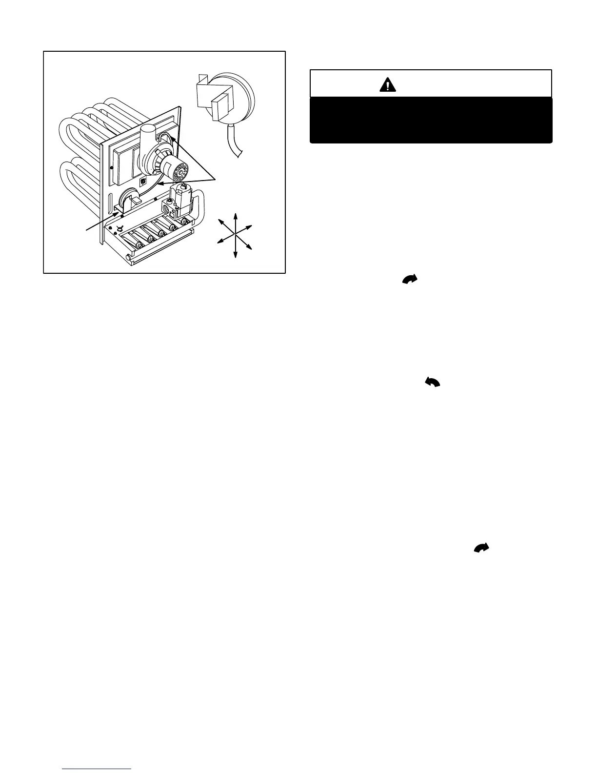
FIGURE 19
PROVE SWITCH
COMBUSTION AIR INDUCER
PROVE SWITCH
Normally Open
Closes on Negative Pressure
PROVE
SWITCH
Sensing Tube
Attaches to Top
Side Of Blower
Top
Bottom
Left
Right
Back
Front
On startĆup, the switch senses that the combustion air
blower is operating. It closes a circuit to the furnace control
when pressure inside the combustion air blower deĆ
creases to a certain set point. Set points vary depending
on unit size. The pressure sensed by the switch is relative
to atmospheric pressure. If the flue becomes obstructed
during operation, the switch senses a loss of negative
pressure (pressure becomes more equal with atmospherĆ
ic pressure) and opens the circuit to the furnace control
and gas valve. A bleed port on the switch allows dry relativĆ
ity air in the vestibule to purge switch tubing, to prevent
condensate build up. The switch also has an internal inline
orifice, designed to prevent nuisance shut downs due to
erratic vent pressure fluctuations.
The switch is factory set and is not field adjustable. It is a
safety shutĆdown control in the furnace and must not be
by-passed for any reason. If switch is closed or by-passed,
the control will not initiate ignition at start up.
II-PLACEMENT AND INSTALLATION
Make sure unit is installed in accordance with installation
instructions and applicable codes.
III-STARTĆUP
A-Preliminary and Seasonal Checks
1 - Inspect electrical wiring, both field and factory installed
for loose connections. Tighten as required.
2 - Check voltage at disconnect switch. Voltage must be
within range listed on the nameplate. If not, consult the
power company and have voltage condition corrected
before starting unit.
B-Heating StartĆUp
WARNING
Shock and burn hazard.
80UHG-1 units are equipped with a direct spark igniĆ
tion system. Do not attempt to light manually.
1 - STOP! Read the safety information at the beginning
of this section.
2 - Set thermostat to lowest setting.
3 - Turn off all electrical power to appliance.
4 - This appliance is equipped with an ignition device
which automatically lights the burners. Do not try to
light the burners by hand.
5 - Remove top access panel.
6 - White Rodgers 36E Gas Valve -- Switch lever to
OFF. See figure 15.
Honeywell VR8205 Gas Valve -- Turn knob on gas
valve clockwise to OFF. Do not force. See figĆ
ure 16.
7 - Wait five (5) minutes to clear out any gas. If you then
smell gas, STOP! Close manual main shut-off valve to
the furnace. Immediately call your gas supplier from a
neighbor's phone. Follow the gas supplier's instructions.
If you do not smell gas go to next step.
8 - White Rodgers 36E Gas Valve -- Switch gas valve lever
to ON.
Honeywell VR8205 Gas Valve -- Turn knob on gas
valve counterclockwise to ON. Do not force.
9 - Replace access panel.
10- Turn on all electrical power to unit.
11- Set thermostat to desired setting.
NOTE–When unit is initially started, steps 1 through 11
may need to be repeated to purge air from pilot line.
12- If the appliance will not operate, follow the instructions
To Turn Off Gas To Unit".
Turning Off Gas To Unit
1 - Set thermostat to lowest setting.
2 - Turn off all electrical power to unit if service is to be
performed.
3 - Remove access panel.
4 - Switch lever on White Rodgers gas valve to OFF; turn
knob on Honeywell valve clockwise to OFF. Do not
force.
5 - Replace access panel.
C-Safety or Emergency Shutdown
Turn off unit power. Close manual and main gas valves.
D-Extended Period Shutdown
Turn off thermostat or set to UNOCCUPIED" mode. Close
all gas valves (both internal and external to unit) to guaranĆ
tee no gas leak into combustion chamber. Turn off power
to unit. All access panels, covers and vent caps must be in
place and secured.

 Loading...


