507621-01 Issue 1720 Page 9 of 23
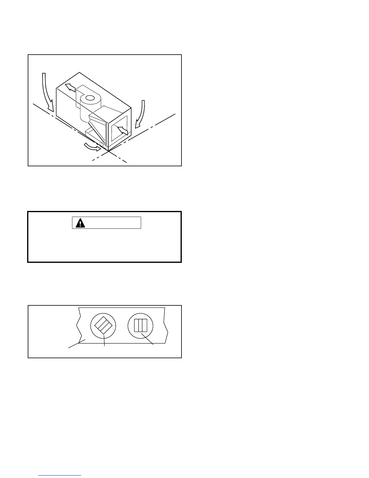
Sloping the Unit
Make sure the unit is sloped (similar to the slope shown in
gure 11) (horizontal or upow) so that the drain pan will
empty completely without water standing in the pan.
THIS CORNER SHOULD BE 5/8” (+/- 1/8”) HIGHER
THAN DRAIN CORNER
DRAIN CORNER
THIS CORNER SHOULD BE
5/8” (+/- 1/8”) HIGHER THAN
DRAIN CORNER
LEVEL PLANE
LEVEL PLANE
Figure 11. Sloping the Drain
Install Condensate Drain
The air handler is equipped with ¾” NPT condensate drain
connections.
On some pans, the primary and secondary drain holes
have knockouts. Conrm primary and secondary drains
are open.
IMPORTANT
1. These units are equipped with a drain pan, which
includes green (main drain) and red (secondary drain)
plugs. Unscrew the plugs to remove them before
inserting condensate drain ttings. See gure 12.
DRAIN PAN
RED SECONDARY
DRAIN PLUG
UNSCREW PLUGS
AND CONNECT
PROPERLY SIZED
FIELD-PROVIDED
FITTINGS AND
DRAIN LINES.
GREEN MAIN
DRAIN PLUG
Figure 12
2. After removal of drain pan plugs, check the drain port
to see if holes have been drilled. If not drilled, use a
19/32” bit to drill out the primary drain hole; use a 3/8”
drill bit for the secondary drain hole. Remove all drill
shavings.
3. Install properly-sized, eld-provided connection ttings
and connect primary drain line to the main drain pan
connection.
NOTE: When installing drain line connection ttings
to the drain pan, hand tighten the tting and use a
thread sealant. Over-tightening the ttings can split
connections on the drain pan.
4. If the secondary drain line is to be used, remove the
plug or the knockout and route the drain line so that
water draining from the outlet will be easily noticed
by the homeowner. Refer to local codes for drain trap
requirements on the secondary drain line.
5. Check again to ensure drain ports and drain pan are
free of all debris.
6. Plug and check any unused drain pan openings for
tightness. Torque plugs to 30 in. lb. to prevent water
leaks or seepage from the drain pan.
7. Install a 2” trap in the main (primary) drain lines as
close to the unit as practical (see gure 10). Make sure
the top of the trap is below the connection to the drain
pan to allow complete drainage of the pan.
NOTE: Horizontal runs must have an anti-siphon air
vent (standpipe) installed ahead of the horizontal run.
See gure 10. An extremely long horizontal run may
require an oversized drain line to eliminate air traps.
NOTE: Do not operate air handler without a trap in
the main (primary) drain. The condensate drain is on
the negative pressure side of the blower; therefore, air
being pulled through the condensate line will not allow
positive drainage without a proper trap.
8. Route the drain line to the outside or to an appropriate
drain. Drain lines must be installed so they do not block
service access to the front of the air handler. A 24”
clearance is required for lter, coil, or blower removal
and service access.
NOTE: Check local codes before connecting the drain
line to an existing drainage system.
9. Insulate the drain lines where sweating could cause
water damage.
Test Condensate Drain
Test the drain pan and drain line after installation:
1. Pour several quarts of water into drain pan. Use
enough water to ll both the drain trap and the line.
2. Check the installed drain pan. Drain pan must be
draining completely. Drain line ttings must not be
leaking. Water must be draining from the end of the
primary drain line.
3. Correct any leaks found.
 Loading...


