Page 15
CHANGE BLOWER SPEED
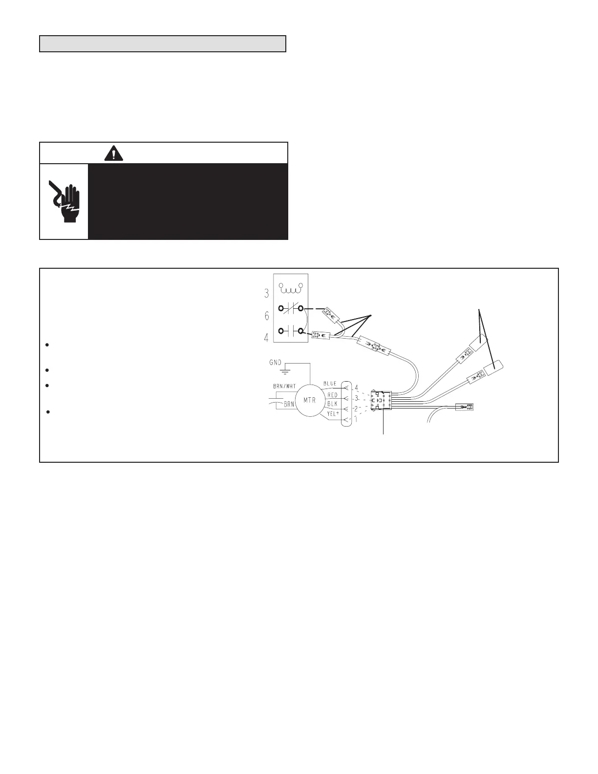
1 - Disconnect all power supplies.
2 - Remove the air handler access panel.
3 - Locate pin number 2 on the blower relay. Two
black wires are connected to this terminal pin. One
connects to pin number 5 on the blower relay, one
connects to an in-line splice connecting to a blue
wire.
4 - Select the required blower motor speed. Connect
red-LO or black-HI and plug it into the 4-pin blower
relay harness connector.
NOTE - Reuse the factory-installed wire nut on the un-
used wires.
5 - Replace all panels.
6 - Reconnect power.
2
BLUE (MED)
RED (L0)
BLACK (HI)
YELLOW (COM)
5
BLOWER RELAY
PLASTIC CAPS
4-PIN
HARNESS
All air data measured external to unit with
25mm non-pleated air filter in place.
All factory settings are medium speed.
All data given while air handler is operating
with a dry DX coil.
All downflow applications run on high speed
when utilizing electric heat.
NOTE - Refer to wiring diagram located on the
unit access panel, this figure and Blower Data
tables in this instruction.
FIGURE 19. Changing Blower Speed
Air Flow – Cooling Blower Speed
The cooling blower speed is factory congured to provide
correct air ow for an outdoor unit that matches the cool-
ing capacity rating of the air handler.
If the outdoor unit is smaller than the maximum cooling ca-
pacity rating for the air handler, the cooling blower speed
may need to be changed. Refer to the Blower Data tables
on pages 17 and 18 .
WARNING
Electric shock hazard! - Disconnect all power
supplies before servicing.
Replace all parts and panels before
operating.
Failure to do so can result in death or
electrical shock.
 Loading...


