Page 4
If a return air plenum is used, the return air grille should be
immediately in front of the opening in the plenum to allow
for the free ow of return air. When not installed in front of
the opening, there must be adequate clearance around
the air handler to allow for the free ow of return air.
Installation
Each unit consists of a blower assembly, refrigerant coil,
and controls in an insulated galvanized steel factory-n-
ished enclosure. Knockouts are provided for electrical wir-
ing entrance.
For ease in installation, it is best to make any necessary
coil conguration changes before setting air handler in
place.
REFRIGERANT METERING DEVICE
CBX25UH units are equipped with a factory-installed
check/ expansion valve.
UPFLOW APPLICATION
1 - The air handler must be supported on the bottom
only and set on solid oor or eld-supplied support
frame. Securely attach the air handler to the oor or
support frame.
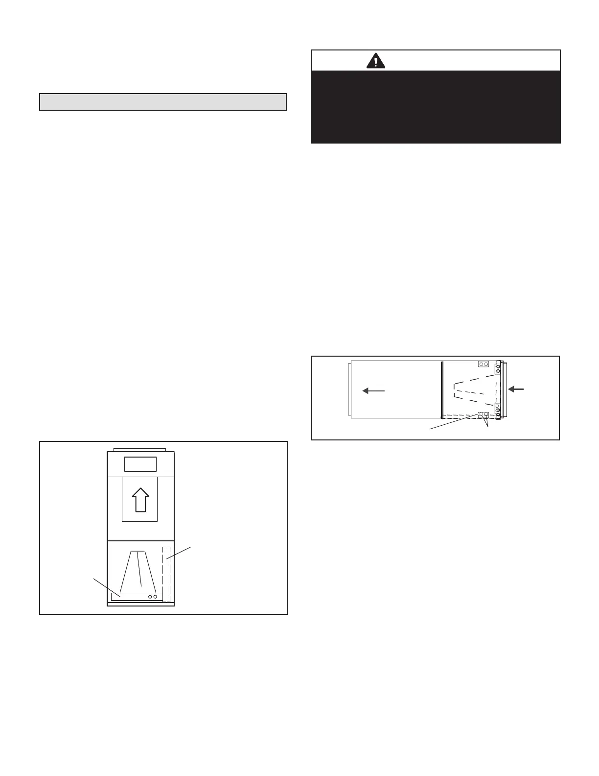
2 - If installing a unit in an upow application, remove
the horizontal drain pan. IMPORTANT - The
horizontal drain pan is not required in upow
air discharge installations; its removal provides
the best efciency and air ow.
3 - Place the unit in the desired location and slope unit.
Connect return and supply air plenums as required
using sheet metal screws.
4 - Install units that have no return air plenum on a
stand that is at least 36cm from the oor. This will
allow proper air return.
HORIZONTAL DRAIN PAN
(MUST BE REMOVED)
UP-FLOW /
DOWN-FLOW
DRAIN PAN
FIGURE 1. Upow Conguration
HORIZONTAL APPLICATIONS
IMPORTANT
When removing the coil, there is a possibility of danger
of equipment damage and personal injury. Be careful
when removing the coil assembly from a unit installed in
right- or left-hand applications. The coil may tip into the
drain pan once it is clear of the cabinet. Support the coil
when removing it..
NOTE - When the unit is installed in horizontal applica-
tions, a secondary drain pan is recommended. Refer to
local codes.
NOTE - This unit may be installed in left-hand or right-
hand air discharge horizontal applications. Adequate sup-
port must be provided to ensure cabinet integrity. Ensure
that there is adequate room to remove service and access
panels if installing in the horizontal position.
LEFT-HAND AIR DISCHARGE
1 - Determine which plugs are required for drain line
connections.
2 - With access door removed, remove drain line plugs
to install drain lines.
3 - Set unit so that it is sloped toward the drain pan end
of the unit (see gure 11).
4 - The horizontal conguration is shown in gure 2.
Drains
AIR FLOW
LEFT‐HAND DRAINS
FIGURE 2. Left-Hand Discharge Conguration
5 - If the unit is suspended, the entire length of the
cabinet must be supported. If you use a chain or
strap, use a piece of angle iron or sheet metal
attached to the unit (either above or below) to
support the length of the cabinet. Use securing
screws no longer than 13mm to avoid damaging the
coil or lter. See gure 3. Use sheet metal screws
to connect the return and supply air plenums as
required.
 Loading...


