Page 17
Check-out Procedures
NOTE – Refer to outdoor unit installation instructions for sys-
tem start-up instructions and refrigerant charging instructions.
PRE-START-UP CHECKS
• Is the air handler properly and securely installed?
• If horizontally congured, is the unit sloped up to 16mm
toward drain lines?
• Will the unit be accessible for servicing?
• Has an auxiliary pan been provided under the unit with
separate drain for units installed above a nished ceil-
ing or in any installation where condensate overow
could cause damage?
• Have ALL unused drain pan ports been properly
plugged?
• Has the condensate line been properly sized, run,
trapped, pitched, and tested?
• Is the duct system correctly sized, run, sealed, and in-
sulated?
• Have all cabinet openings and wiring been sealed?
• Is the indoor coil factory-installed TXV properly sized for
the outdoor unit being used?
• Have all unused parts and packaging been disposed
of?
• Is the lter clean, in place, and of adequate size?
• Is the wiring neat, correct, and in accordance with the
wiring diagram?
• Is the unit properly grounded and protected (fused)?
• Is the thermostat correctly wired and in a good location?
• Are all access panels in place and secure?
CHECK BLOWER OPERATION
• Set thermostat to FAN ON.
• The indoor blower should come on.
CHECK COOLING OPERATION
• Set thermostat to force a call for cooling (approximately
2ºC lower than the indoor ambient temperature).
• The outdoor unit should come on immediately and the
indoor blower should start between 30 - 60 seconds lat-
er.
• Check the air ow from a register to conrm that the
system is moving cooled air.
• Set the thermostat 2ºC higher than the indoor tempera-
ture. The indoor blower and outdoor unit should cycle
off.
Operation
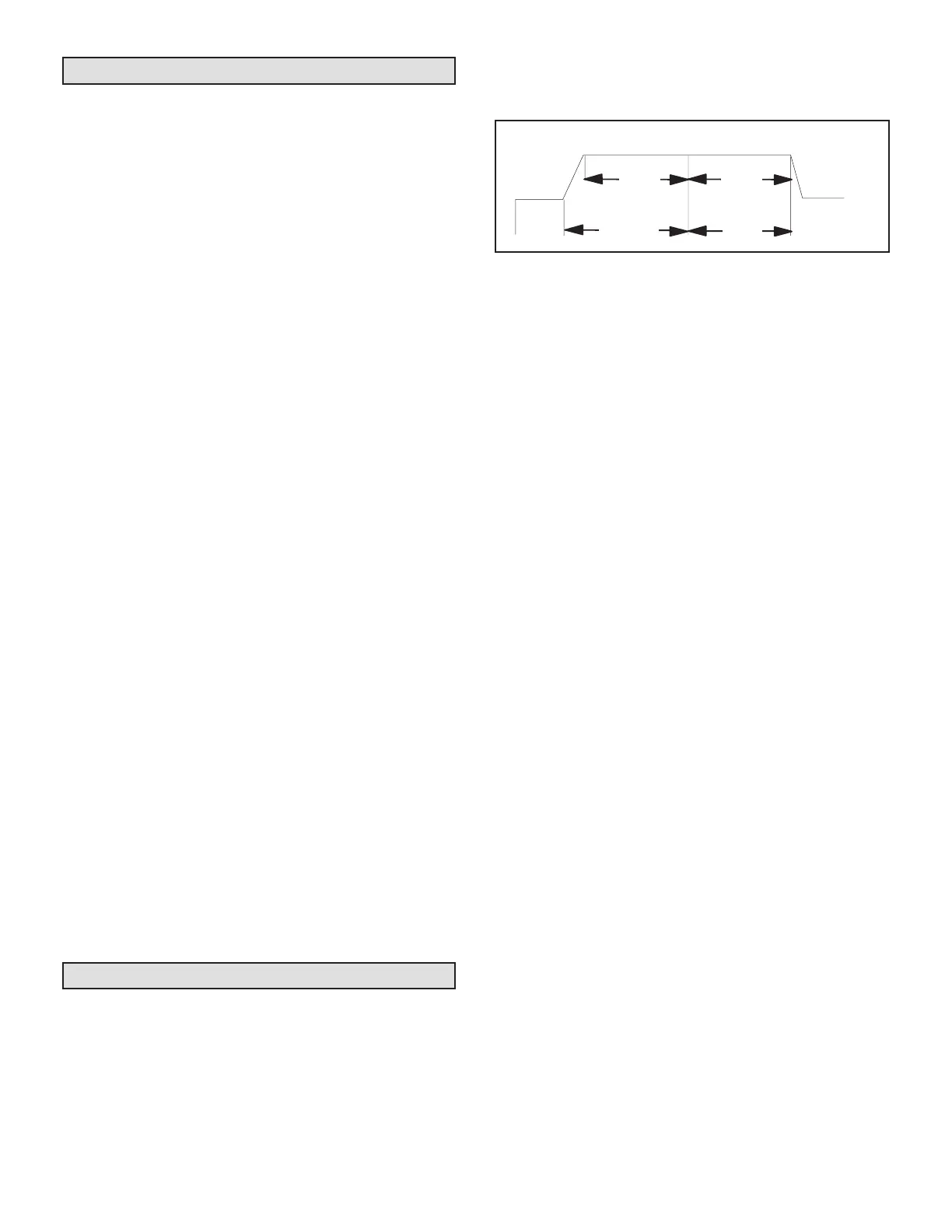
TIME DELAY RELAY
Blower time delay operation:
1 - When cooling demand is initiated, there is a 1
second motor-on delay.
2 - After the motor-on delay expires, motor ramps up
to 100% and runs at 100% until cooling demand is
satised.
3 - Once demand is met, motor runs at 100% for 45
seconds.
4 - Motor ramps down to stop.
1
SECOND
DELAY
OFF
100%
L/s
100%
L/s
45
COOLING
1
2
FIGURE 20. Blower Time Delay
COOLING (COOLING ONLY OR HEAT PUMP)
When the thermostat calls for cooling, 24 volts is put on
the blower time-delay relay coil and then the indoor blow-
er relay energizes. The normally open contacts close,
causing the indoor blower motor to operate. The circuit
between R and Y is completed, closing the circuit to the
contactor in the outdoor unit, starting the compressor and
outdoor fan motor.
On heat pumps, circuit R and O energizes the reversing
valve, switching the valve to the cooling position. (The re-
versing valve remains energized as long as the thermo-
stat selector switch is in the COOL position.)
At the completion of the cooling demand the indoor blower
and outdoor unit should cycle off. Air handler should cycle
off 45 seconds after the outdoor unit shuts off.
HEATING (HEAT PUMP)
When the thermostat calls for heating, 24 volts is applied
to the blower time-delay relay coil. Then, normally open
contacts close, causing the indoor blower motor to oper-
ate. The circuit between R and Y is completed, closing
the circuit to the contactor in the outdoor unit, starting the
compressor and outdoor fan motor.
If the room temperature continues to decrease, the cir-
cuit between R and W1 is completed by the second-stage
heat room thermostat. Circuit R-W1 energizes a heat se-
quencer. The completed circuit will energize supplemen-
tal electric heat (if applicable). Units with a second heat
sequencer can be connected with the rst sequencer to
W1 on the thermostat. They may also be connected to
a second heating stage W2 on the thermostat sub-base.
EMERGENCY HEAT (HEATING HEAT PUMP)
If the selector switch on the thermostat is set to the emer-
gency heat position, the heat pump will be locked out of
the heating circuit, and all heating will be electric heat (if
applicable). A jumper should be placed between W2 and E
on the thermostat sub-base so that the electric heat con-
trol will transfer to the rst-stage heat on the thermostat.
This will allow the indoor blower to cycle on and off with the
electric heat when the fan switch is in the AUTO position.
 Loading...


