Page 5
FRONT WEIV DNEWEIV
ANGLE IRON OR SHEET
METAL
ANCE 102 MM
MAXIMUM 13 MM
LONG SCREW
AIR FLOW
FIGURE 3. Suspending Horizontal Unit
RIGHT-HAND AIR DISCHARGE
For horizontal right-hand air discharge, the following eld
modications are required.
1 - Remove and set aside blower and coil access
panels.
2 - Remove brackets securing pan to unit. See gure 4.
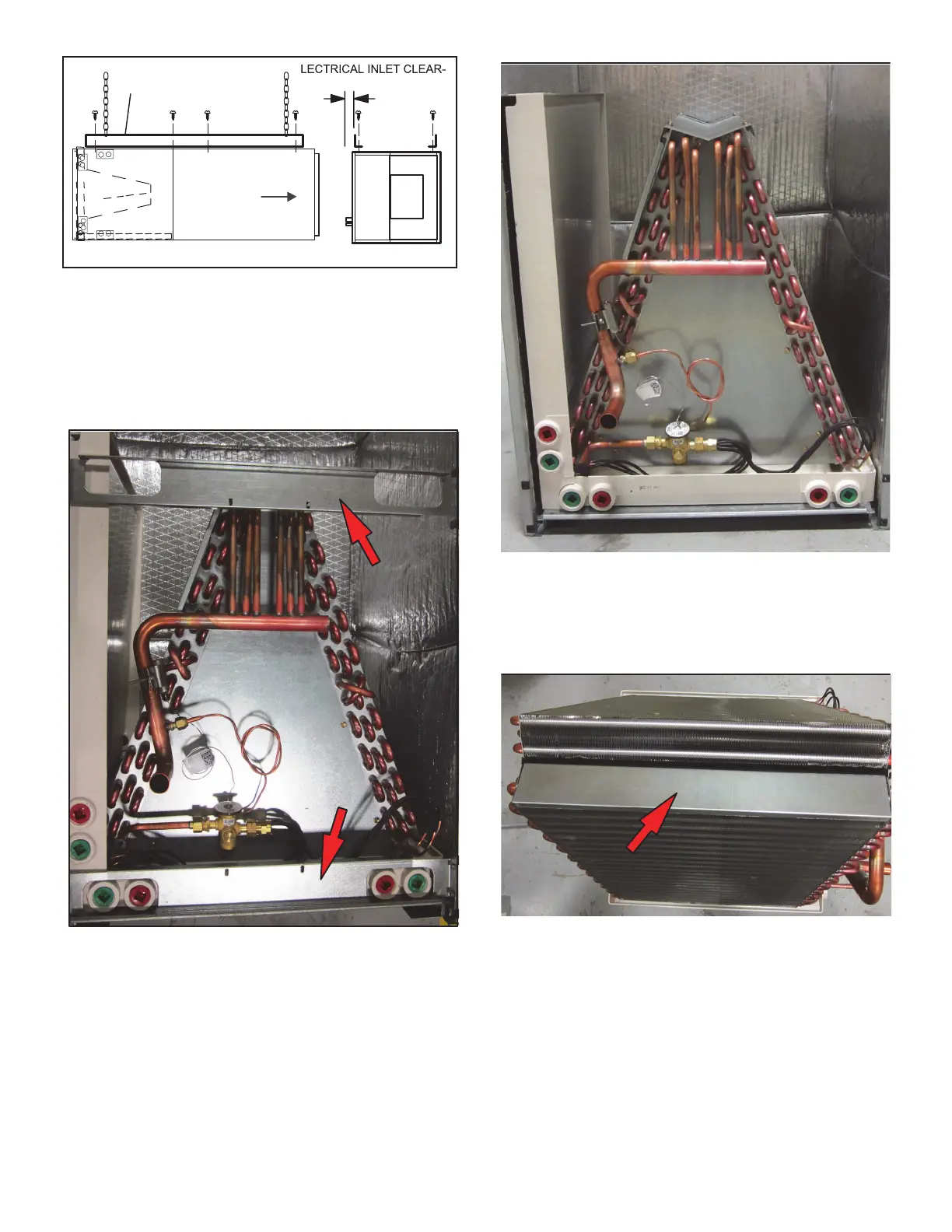
FIGURE 4. Remove Main Drain Pan
Mounting Brackets
3 - Remove coil assembly, bottom drain pan and
horizontal drain pan as one unit from the air handler.
FIGURE 5. Remove Coil Assembly, Bottom Drain Pan
and Horizontal Drain Pan as a Unit
4 - Remove the blow-off prevention brackets, top cap
and drip pan between slabs. Move the horizontal
drain pan to the opposite side of the coil.
FIGURE 6. Remove Blow-Off Prevention Brackets,
Top Cap and Drip Pan
5 - Rotate drip pan 180º and reinstall on coil as shown
by the arrow above. Reinstall the top cap. Rotate
the blow-off prevention brackets 180º and reinstall
using the same screws. Use the correct mounting
holes; the brackets must cover the hairpins. See
gure 7.
 Loading...


