Page 7
CBX27UH SERIES
AIR HANDLER UNIT
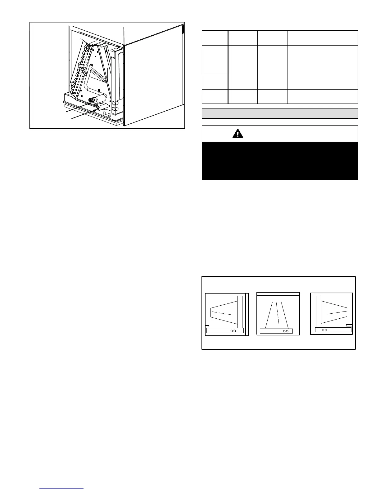
SUCTION LINE
LIQUID LINE
Figure 6. Brazing Connections
NOTE − CBX27UH series air handlers use nitrogen or
dry air as a holding charge. If there is no pressure when
the rubber plugs are removed, check the coil for leaks
before installing. After installation, pull a vacuum on the
line set and coil before releasing the unit charge into the
system.
NOTE − See outdoor unit instructions on how to flow
nitrogen through line sets.
1. Remove access panel.
2. Remove the refrigerant line caps from the refrigerant
lines.
3. Use a wet rag to protect TXV sensing bulb (or remove
it) when brazing suction line connections.
4. Place a wet rag against piping plate and around the
suction line connection. The wet rag must be in place
to guard against damage to the paint.
5. With the wet rag in place, position a field provided
elbow fitting to the air handler’s suction line and line
set. Start nitrogen flow before brazing.
6. After the procedure is completed then remove the wet
rag.
7. Place wet rag against piping plate and around the
liquid line connection. Position liquid line elbow to air
handler’s suction line and to line set. Start nitrogen flow
and begin brazing both connections and after
procedure is completed then remove both wet rags.
8. Refer to instructions provided with outdoor unit for leak
testing, evacuating and charging procedures.
9. Install access panel.
Table 2. Refrigerant Line Sizes
Model
Liquid
Line
Vapor
Line
Line Sets
−018
−024
−030
−036
3/8"
(10mm)
3/4"
(19mm)
L15 line set sizes are depen-
dent on unit match−up. See
Engineering Handbook for
outdoor unit to determine cor-
rect line set sizes.
−042
−048
3/8"
(10mm)
7/8"
(22mm)
−060
3/8"
(10mm)
7/8"
(22mm)
Field-fabricated
Installing the Condensate Drain
IMPORTANT
After removal of drain pan plug(s), check drain hole(s) to
verify that drain opening is fully open and free of any
debris. Also check to make sure that no debris has fallen
into the drain pan during installation that may plug up the
drain opening.
MAIN DRAIN
Connect the main drain and route downward to drain line or
sump. Do not connect drain to a closed waste system. See
Figure 8 for typical drain trap configuration.
OVERFLOW DRAIN
It is recommended that the overflow drain is connected to a
overflow drain line for all units. If overflow drain is not
connected, it must be plugged with provided cap.
For downflow orientation, the overflow drain MUST be
connected and routed to a overflow drain line. See Figure 8
for main and overflow drain locations based on coil
orientation.
LEFT−HAND AIR
DISCHARGE
MAIN DRAIN ON
RIGHT
OVERFLOW
DRAIN ON LEFT
UPFLOW OR
DOWNFLOW
RIGHT−HAND AIR
DISCHARGE
Figure 7. Main and Overflow Drain Locations based
on Coil Orientation

 Loading...


