Page 11
CBX27UH SERIES
Making Electrical Connections
WARNING
Run 24V Class II wiring only through specified low volt-
age opening. Run line voltage wiring only through speci-
fied high voltage opening. Do not combine voltage in one
opening.
CAUTION
USE COPPER CONDUCTORS ONLY.
This unit is provided with knock-outs for conduit. Refer to
figure 12 on page 13 for unit wiring diagram, which includes
all field wiring. Separate openings have been provided for
24V low voltage and line voltage. Refer to the dimension
illustration on page 2 or 3 for specific location.
Wiring must conform to the current National Electric Code
ANSI/NFPA No. 70, or Canadian Electric Code Part I, CSA
Standard C22.1, and local building codes. Refer to
following wiring diagrams. See unit nameplate for
minimum circuit ampacity and maximum overcurrent
protection size.
Select the proper supply circuit conductors in
accordance with tables 310−16 and 310−17 in the
National Electric Code, ANSI/NFPA No. 70 or tables 1
through 4 in the Canadian Electric Code, Part I, CSA
Standard C22.1.
The motor speed is set by the speed tap connection to the
low voltage terminal strip in the control section. The speed
can be increased by swapping wires as shown in figure 10.
WIRING CONNECTIONS
1. Install line voltage power supply to unit from a properly
circuit breaker.
2. Ground unit at unit disconnect switch or to an earth
ground.
NOTE Connect conduit to the unit using a proper
conduit fitting. Units are approved for use only with
copper conductors. A complete unit wiring diagram is
located on the back side of the unit’s access panel.
3. Install low voltage wiring from outdoor to indoor unit
and from thermostat to indoor unit.
NOTE For proper voltages, select thermostat wire
gauge per the following chart:
Table 7. Run Length (Class II Rated Wiring)
Wire Run Length AWG # Insulation/Core Types
Less than 100’ (30m) 18
Color−coded, temperature
rating 95
º
F (35
º
C) minimum,
solid core.
More than 100’ (30m) 16
NOTE Units are approved for use only with copper conductors.
Ground unit at disconnect switch or to an earth ground.
NOTE 24VAC, Class II circuit
connections are made in the con-
trol panel.
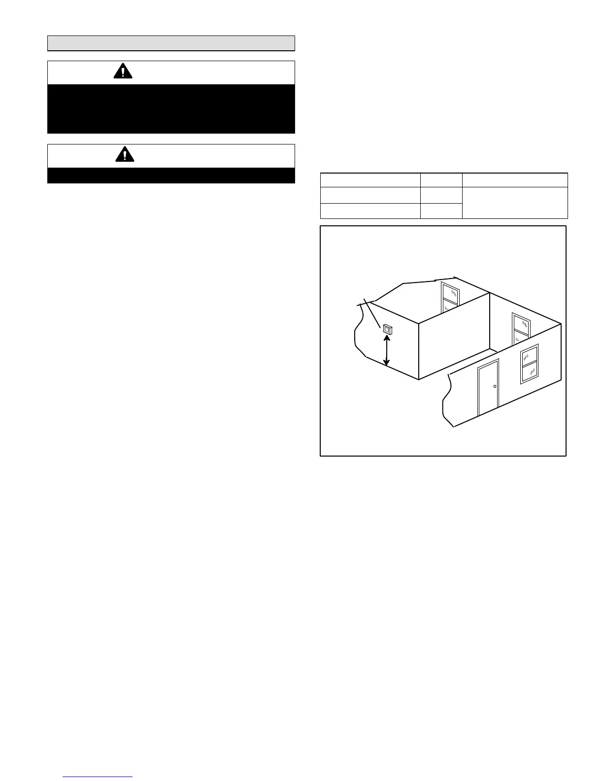
Install room thermostat (ordered separately) on an inside wall
approximately in the center of the conditioned area and 5 feet (1.5m)
from the floor. It should not be installed on an outside wall or where it
can be affected by sunlight or drafts.
THERMOSTAT
5 FEET
(1.5M)

 Loading...


