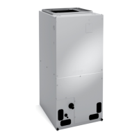
CBX32MV / Page 3
REFRIGERANT SYSTEM (continued)
Flared shoulder tubing joints and silver soldering
provide tight, leakproof joints.
Coil thoroughly factory tested under high pressure to
insure leakproof construction.
Refrigerant Line Connections
Suction (vapor) and liquid lines have sweat connections
that extended outside of the cabinet for ease of
connection.
See dimension drawings for locations.
Check and Expansion Valve Furnished
For use with R-410A systems.
Wide range valve with Chatleff
style tting.
Factory installed on all models, internal to cabinet.
CABINET
Constructed of heavy-gauge galvanized steel.
Completely insulated with thick berglass insulation.
Pre-painted steel cabinets have mildly textured enamel
nish with primer coat on unpainted side of all panels.
Units are shipped in one piece but may be
disassembled into two separate sections for ease
of installation in tight applications. See dimension
drawings.
Thick rubber gasket between sections of the two piece
cabinets provides an air tight seal.
No external screw heads on sides of cabinet for tight
installations without damage to walls or woodwork.
Removable panels provide complete service access.
Electrical inlets provided in sides and top of cabinet.
See dimension drawings for locations.
Low Leakage Cabinet
All models have less than 2% air leakage and meet
ANSI/ASHRAE Standard 193-2010 “Method of Test for
Determining the Air Tightness of HVAC Equipment”.
Multi-Position Capability
Shipped for upow and horizontal right-hand discharge.
Quickly converted to downow or left-hand, horizontal
air discharge.
Easily converts to downow position with furnished coil
support rails and lter support rack.
Dual Position Drain Pans
Drain pans designed for upow, downow or horizontal
applications.
Deep, corrosion resistant plastic drain pans have dual
pipe drains.
See dimension drawings.
C
D
E
Optional Accessories
Downow Combustible Flooring Base
Base is required for models with electric heat installed in
downow position on combustible oors.
Horizontal Support Frame Kit (Not for -068)
Provides support of unit in horizontal applications.
Consists of (2) 1 x 1-1/2 x 32-5/8 in. and (2) 1 x 3 x
53-7/8 in. painted heavy gauge cold rolled steel support
channels with assembly and suspending holes.
Bolts and nuts furnished for eld assembly.
Suspending rods must be eld provided.
Side Return Unit Stand (Upow Only, Not for -068)
Raises unit 16 in. above oor for side return air duct
connection.
Eliminates need for wooden platform construction.
All aluminum construction.
Two adjustable frames t -018/024 thru -060 models.
Wall Hanging Bracket Kit (Upow Only)
Allows unit to be hung on wall at any height.
Consists of heavy-gauge steel support brackets (one for
air handler, one for wall mount).
Screws furnished for fastening one bracket to unit.
Bolts for fastening one bracket to wall are eld provided.
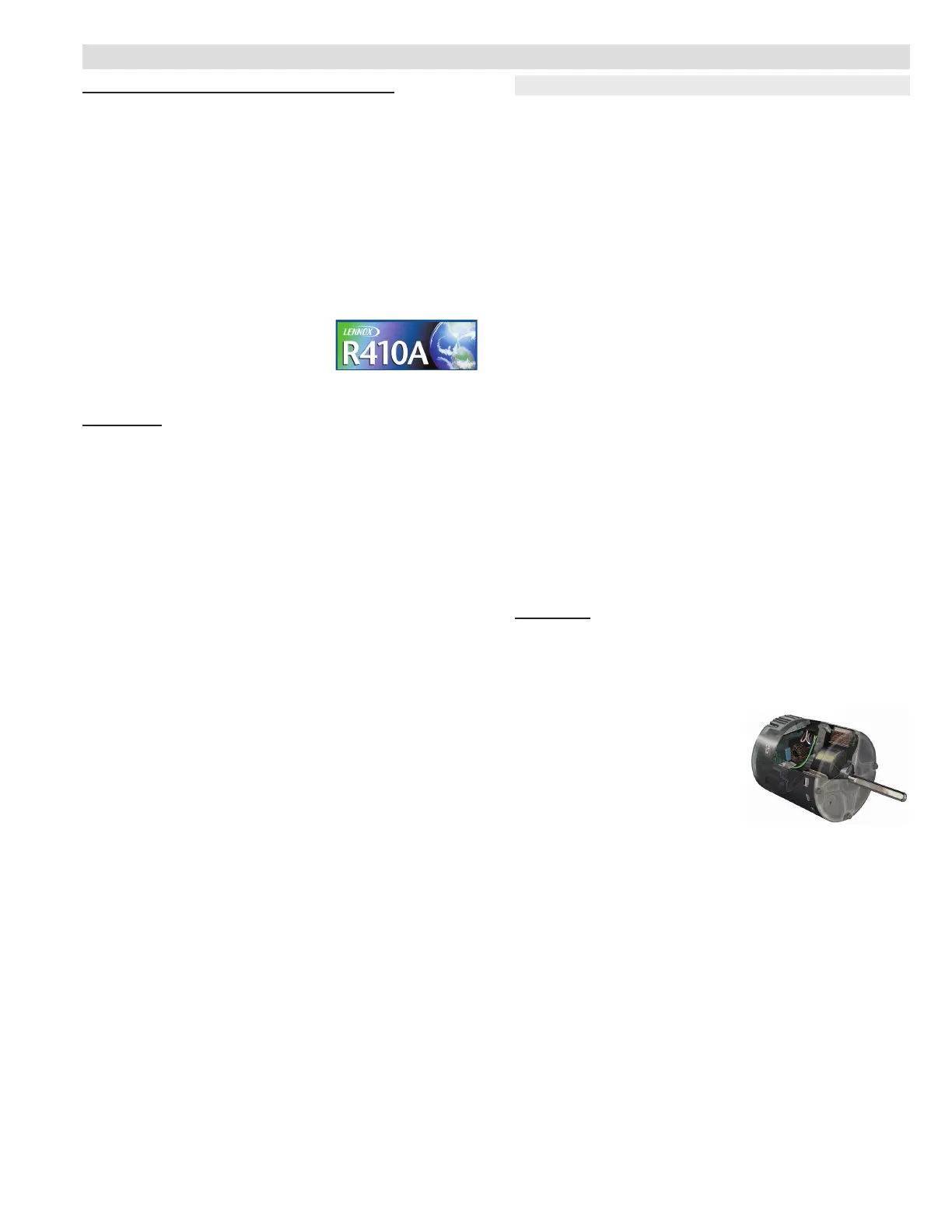
BLOWER
Variable-Speed Blower Motor
High efciency multi-speed blower motor maintains
specied air volumes up to a maximum of 0.8 in. w.g.
total external static.
Multi-speed operation is
achieved by the use of an ECM
(Electronically Commutated
Motor) motor.
Allows cooling ramping proles
(eld selectable) for enhanced
dehumidication.
Motor accelerates and decelerates gradually, reducing
start-up and shut-down sound.
Leadless blower motor features simple plug-in
connections.
Motor is controlled by the iComfort
®
control that allows
blower to operate at two of eight air volumes or speeds
available.
Speeds may be eld selected on iComfort
®
control
depending on size of air handler and air volume desired.
See blower performance tables.
Blower Assembly
Lennox designed and built, direct drive blower.
Each blower is statically and dynamically balanced as
an assembly before installation in the unit.
Blower motor is resiliently mounted to blower assembly.
Blower slides out of cabinet for servicing.
F
G
FEATURES
3 of 44 B17-0056
01/19/2017

 Loading...