EasyManua.ls Logo

Lennox BCE3M*C SERIES User Manual

Lennox BCE3M*C SERIES
23 pages
To Next Page IconTo Next Page
Page #1 background imageLoading...
Page #1 background image
507621-01 Issue 1720 Page 1 of 23
This is a safety alert symbol and should never be ignored. When you see this symbol on labels or in
manuals, be alert to the potential for personal injury or death.
These instructions must be read and understood completely before attempting installation.
THIS MANUAL MUST BE LEFT WITH THE
HOMEOWNER FOR FUTURE REFERENCE
Table of Contents
Unit Dimensions ..........................................................2
Shipping and Packing List ...........................................3
General ........................................................................3
Requirements ..............................................................3
Installation Clearances ................................................4
Installation ...................................................................4
Condensate Drain........................................................8
Duct System and Filters ............................................10
Brazing Refrigerant Lines .......................................... 11
Sealing the Unit .........................................................13
Electrical Connections ...............................................13
Air Flow — Cooling Blower Speed ............................17
Check-Out Procedures ..............................................19
Operation ...................................................................19
Maintenance ..............................................................20
Cabinet Insulation ......................................................20
Use of Air Handler During Construction.....................21
Improper installation, adjustment, alteration, service
or maintenance can cause property damage, personal
injury or loss of life. Installation and service must be
performed by a licensed professional installer (or
equivalent), service agency or the gas supplier.
WARNING
215 Metropolitan Drive
West Columbia, SC 29170
*P507621-01*
(P) 507621-01
INSTALLATION INSTRUCTIONS
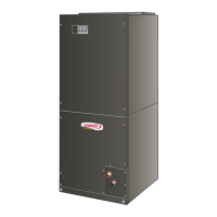
BCE3M*C & BCS3M*C SERIES AIR HANDLER
This product contains a chemical known to the State
of California to cause cancer, birth defects or other
reproductive harm.
WARNING
The Clean Air Act of 1990 bans the intentional venting
of refrigerant (CFCs, HCFCs and HFCs) as of July
1, 1992. Approved methods of recovery, recycling or
reclaiming must be followed. Fines and/or incarceration
may be levied for noncompliance.
CAUTION
Question and Answer IconNeed help?

Do you have a question about the Lennox BCE3M*C SERIES and is the answer not in the manual?

Lennox BCE3M*C SERIES Specifications

General IconGeneral
BrandLennox
ModelBCE3M*C SERIES
CategoryAir Handlers
LanguageEnglish

Summary

Unit Dimensions

Shipping and Packing List

General

Requirements

Installation Clearances

Non-Ducted Return Closet Installation

Specifies clearance requirements for closet installations, including minimum open area for louvers.

Installation

General Information

Details factory configuration, coil changes, knockouts, and placement considerations for installation.

Upflow Application

Horizontal Applications

Left-Hand Air Discharge

Steps for left-hand horizontal discharge: drain line connections, sloping, and suspension if needed.

Right-Hand Air Discharge

Condensate Drain

Typical Main and Overflow Drain

Illustrates and explains primary/secondary drain lines, traps, vents, and secondary drain pan requirements.

Sloping the Unit

Install Condensate Drain

Test Condensate Drain

Procedure to test the drain pan and line after installation, checking for leaks and complete drainage.

Duct System and Filters

Duct System

Instructions for connecting duct systems, insulation, and plenum extension for optimal airflow.

Filters

Details on provided filters, filter sizing table, and impact of high-efficiency filters on performance.

Installing Duct System

Guidance on installing plenums, ducts, and filters per NFPA 90B standards.

Field-Fabricated Return Air Duct Flange for Horizontal Applications

Instructions for fabricating a return air duct flange for horizontal applications in confined spaces.

Brazing Refrigerant Lines

Sealing the Unit

Electrical Connections

208 Volt Conversion

Low Voltage Connections

Air Flow - Cooling Blower Speed

Change Blower Speed

Instructions to change the cooling blower speed by reconfiguring wires on the blower relay.

Check-Out Procedures

Pre-Start-Up Checks

A comprehensive checklist for ensuring the air handler is correctly installed and ready for operation.

Check Blower Operation

Procedure to verify the indoor blower operates when the thermostat is set to FAN ON.

Check Cooling Operation

Steps to test the cooling cycle, including system response and shutdown timing.

Check Electric Heater (if used)

Procedure to test electric heating operation and sequencer function.

Operation

Time Delay Relay

Explanation of the blower time delay relay operation during cooling demand and post-demand.

Cooling (Cooling Only or Heat Pump)

Details on how the unit functions during a cooling call, including blower and outdoor unit engagement.

Heating (Electric Heat Only)

Description of unit operation for electric heat, including sequencer and blower engagement.

Heating (Heat Pump)

Emergency Heat (Heating Heat Pump)

Procedure for engaging emergency heat on heat pumps, including thermostat jumper settings.

Cabinet Insulation

Repairing Damaged Insulation

Instructions for repairing damaged insulation to prevent condensation and maintain unit efficiency.

Use of Air Handler During Construction

Start-Up and Performance Checklist

Related product manuals