507621-01 Issue 1720 Page 5 of 23
For all performance testing, units must be tested in the
upow orientation with the horizontal drain pan removed.
Refrigerant Metering Device
These units are equipped with a factory-installed metering
device (TXV or piston). Ensure the indoor coil metering
device is properly sized for the outdoor unit being used.
Upow Application
1. The air handler must be supported on the bottom only
and set on solid oor or eld-supplied support frame.
Securely attach the air handler to the oor or support
frame.
2. If installing a unit in an upow application, remove the
horizontal drain pan.
IMPORTANT - The horizontal drain pan is not required
in upow air discharge installations; its removal
provides the best efciency and air ow.
3. Place the unit in the desired location and slope unit.
Connect return and supply air plenums as required
using sheet metal screws.
4. Install units that have no return air plenum on a stand
that is at least 14” from the oor. This will allow proper
air return.
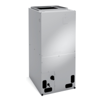
Figure 1. Upow Conguration
HORIZONTAL DRAIN PAN
IMPORTANT - REMOVE PAN
FOR BEST EFFICIENCY
AND AIR FLOW.
UP-FLOW
DRAIN PAN
UP-FLOW DRAIN
CONNECTIONS (BOTH
SIDES; USE ONE SIDE
OR OTHER)
HORIZONTAL DRAIN
CONNECTIONS
(BOTH SIDES; NOT
USED)
Horizontal Applications
When removing the coil, there is possible danger of
equipment damage and personal injury. Be careful
when removing the coil assembly from a unit installed
in right- or left-hand applications. The coil may tip into
the drain pan once it is clear of the cabinet. Support the
coil when removing it.
IMPORTANT
NOTE: When the unit is installed in horizontal applications,
a secondary drain pan is recommended. Refer to local
codes.
NOTE: This unit may be installed in left-hand or right-hand
air discharge horizontal applications. Adequate support
must be provided to ensure cabinet integrity. Ensure that
there is adequate room to remove service and access
panels if installing in the horizontal position.
Left-Hand Air Discharge
1. Determine which plugs are required for drain line
connections.
2. With access door removed, remove drain line plugs to
install drain lines.
3. Set unit so that it is sloped toward the drain pan end of
the unit (see gure 11).
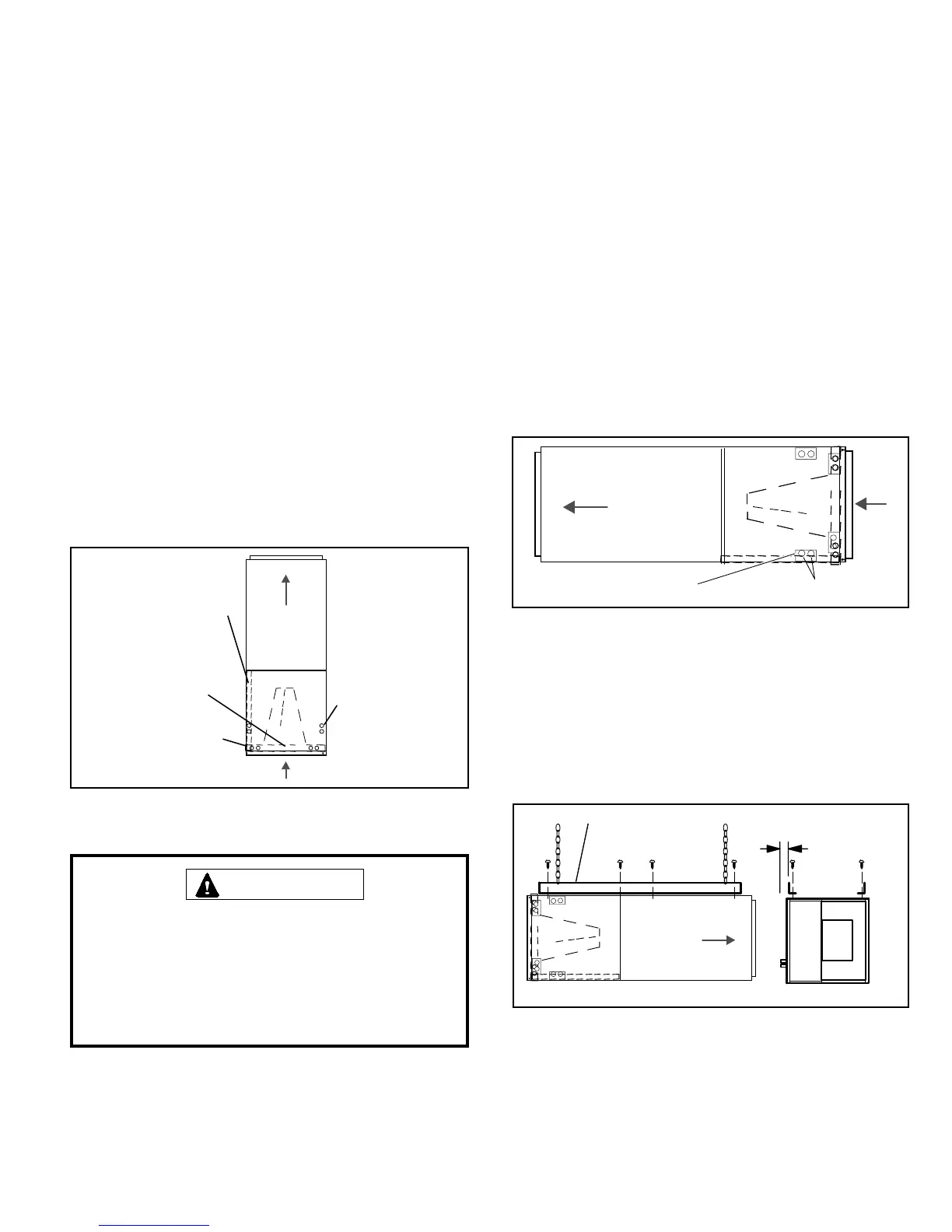
4. The left-hand air discharge horizontal conguration is
shown in gure 2.
Drains
AIR FLOW
PLUGS
LEFT‐HAND DRAINS
Figure 2. Left-Hand Discharge Conguration
5. If the unit is suspended, the entire length of the cabinet
must be supported. If you use a chain or strap, use a
piece of angle iron or sheet metal attached to the unit
(either above or below) to support the length of the
cabinet. Use securing screws no longer than 1/2 inch
to avoid damaging the coil or lter. See gure 3. Use
sheet metal screws to connect the return and supply
air plenums as required.
FRONT VIEW
ANGLE IRON OR SHEET METAL
4 IN. (102 MM)
MAXIMUM 1/2”
LONG SCREW
AIR FLOW
ELECTRICAL INLET CLEARANCE
END VIEW
Figure 3. Suspending Horizontal Unit
 Loading...


