Page 16
humidity from the inside air. Have your dealer show
you the location of the drain line and how to check for
obstructions. (This would also apply to an auxiliary
drain, if installed.)
Thermostat Operation
See the iComfort Wi-Fi
®
thermostat homeowner manual
for instructions on how to operate your thermostat.
Heat Pump Operation
Your new Lennox heat pump has several characteristics
that you should be aware of:
S Heat pumps satisfy heating demand by delivering
large amounts of warm air into the living space. This
is quite different from gas‐ or oil‐fired furnaces or an
electric furnace which deliver lower volumes of
considerably hotter air to heat the space.
S Do not be alarmed if you notice frost on the outdoor coil
in the winter months. Frost develops on the outdoor
coil during the heating cycle when temperatures are
below 45F (7C). The heat pump control activates a
defrost cycle lasting 5 to 15 minutes at preset intervals
to clear the outdoor coil of the frost.
S During the defrost cycle, you may notice steam rising
from the outdoor unit. This is a normal occurrence.
The thermostat may engage auxiliary heat during the
defrost cycle to satisfy a heating demand; however,
the unit will return to normal operation at the
conclusion of the defrost cycle.
Preservice Check
If your system fails to operate, check the following before
calling for service:
S Verify room thermostat settings are correct.
S Verify that all electrical disconnect switches are ON.
S Check for any blown fuses or tripped circuit breakers.
S Verify unit access panels are in place.
S Verify air filter is clean.
S If service is needed, locate and write down the unit
model number and have it handy before calling.
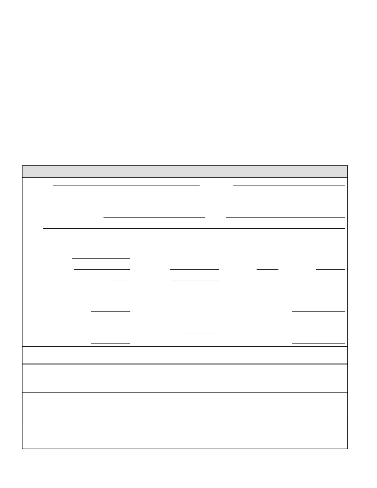
XP25 Start-Up and Performance Checklist
Customer Address
Indoor Unit Model Serial
Outdoor Unit Model Serial
Solar Module Mfg and Model Serial
Notes:
START-UP CHECKS
Refrigerant Type:
Rated Load Amps Actual Amps Rated Volts Actual Volts
Condenser Fan Full Load Amps Actual Amps:
COOLING MODE
Vapor Pressure: Liquid Pressure:
Supply Air Temperature: Ambient Temperature: Return Air Temperature:
HEATING MODE
Vapor Pressure: Liquid Pressure:
Supply Air Temperature: Ambient Temperature: Return Air Temperature:
System Refrigerant Charge (Refer to manufacturer's information on unit or installation instructions for required
subcooling and approach temperatures.)
Subcooling:
A — B = SUBCOOLING
Saturated Condensing Temperature (A)
minus Liquid Line Temperature (B)
Approach:
A — B = APPROACH
Liquid Line Temperature (A)
minus Outdoor Air Temperature (B)
Indoor Coil Temp. Drop (18 to 22°F)
A — B = COIL TEMP DROP
Return Air Temperature (A)
minus Supply Air Temperature (B)
44 of 44 B17-0056
01/19/2017

 Loading...