Page 60
STATUS CODES:
When the compressor is running, the 7-segment display will show the compressor capacity. When the EL23XCV unit is in-
stalled with a conventional 24VAC non-communicating thermostat the display will show C 1 or C 2. When the EL23XCV unit
is installed with an S30/S40 communicating thermostat the display will show the demand as a precentage. i.e. C 5 0.
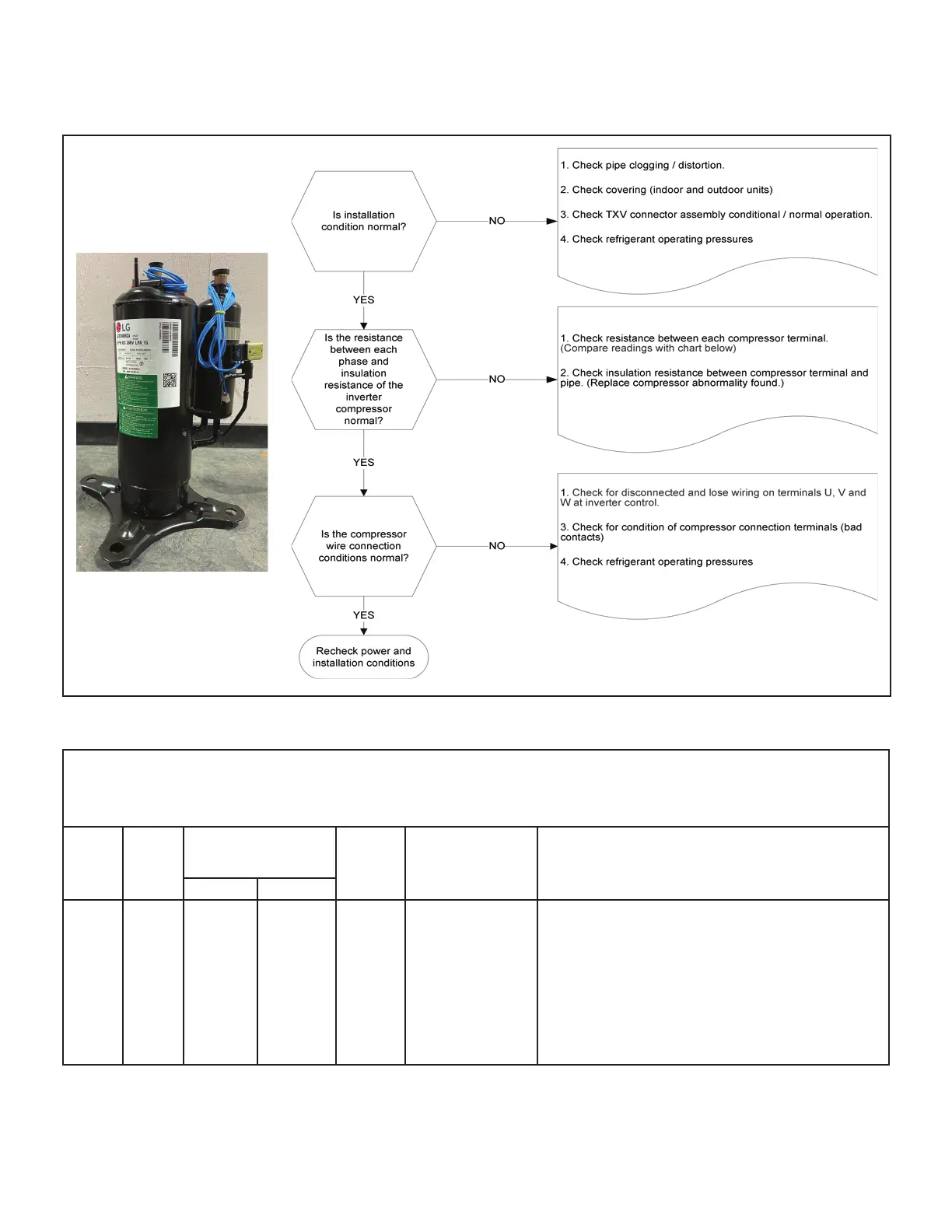
FIGURE 32. Compressor Operation, Checkout and Status/Error Codes
ERROR CODES:
TABLE 13. Outdoor Control 7-Segment Display Alert Codes - Compressor
System fault and lockout codes take precedence over system status codes (cooling, heating operating percentages or defrost/dehumidication). Only
the latest active fault or lockout codes are displayed (if present). If no fault or lockout codes are active, then system status codes are displayed. Alert
codes are also displayed on the S30/S40 thermostat on systems installed with the S30/S40 thermostat.
Alert
Codes
Inverter
Code
Inverter LED Flash
Code (number of
ashes)
Priority Alarm Description Possible Causes and Clearing Alarm
Red LED Green LED
E 430 26 2 ashes 6 ashes
Moderate
/ Critical
Compressor start
failure
If condition is detected, outdoor unit compressor and fan stop.
Antishort cycle is initiated. If condition occurs 10 times within
an hour, system is locked out.
Indicates poor connection at compressor harness, improper
winding resistance, locked compressor rotor, or ooded
compressor.
To clear, disconnect power to the indoor unit (24VAC power
source to the outdoor control) which will power o the outdoor
control and will open the outdoor unit contactor, which
interrupts power to the inverter and then re-apply power.
 Loading...


