Page 66
CHECKOUT:
VAC Voltage Check
Check for 208/240 VAC power at inverter contactor (red wires) (see gure 44).
All EL23XCV Units
1. With the unit running, check for 230VAC at the red outdoor fan motor wires at the contactor. If no voltage is present
check main power at the contactor.
2. Perform a DC voltage check between the FPWM and Fan C terminal.
3. Using the push button on the control, enter the "fan test mode" in the "eld test mode" by pushing and holding the button
until solid "-" appears, release the button. Display will start ashing, within 10 seconds, push and hold the button until
the "F" symbol displays then release the button. Display will begin to ash "F", within 10 seconds, push and hold the
button until it stops ashing, release the button. Outdoor fan motor will cycle on for 10 minutes. To exit, push and hold
the button until three horizontal bars display. Release the button and the outdoor fan will cycle o.
NOTE-
IF ANY WIRE IN THIS APPLIANCE IS REPLACED,IT
MUST BE REPLACED WITH WIRE OF LIKE SIZE,
RATING, INSULATION THICKNESS, AND TERMINATION.
EQUIPMENT
GROUND
DENOTES OPTIONAL COMPONENTS
LINE VOLTAGE FIELD INSTALLED
CLASS II VOLTAGE FIELD WIRING
2
Supersedes
Litho U.S.A.
C
1
RT13
AMBIENT
SENSOR
S87 LOW
PRESSURE
SWITCH
U
V
W
B1
COMPRESSOR
S4 HIGH
PRESSURE
SWITCH
TP
HPS
LPS
LIQ
AMB
COIL
B4
FAN
K1-2
3
COMPRESSOR
CONTACTOR
S40
HR1
CRANKCASE
THERMOSTAT
CRANKCASE
HEATER
RT36
LIQUID
SENSOR
LENNOX
NOTE-
FOR USE WITH COPPER CONDUCTORS
ONLY. REFER TO UNIT RATING PLATE
FOR MINIMUM CIRCUIT AMPACITY AND
MAXIMUM OVERCURRENT PROTECTION SIZE
REFER TO COMPRESSOR IN UNIT FOR
ACTUAL TERMINAL ARRANGEMENT
COMPRESSOR
CONTACTOR
RED
L2
2
K1-1
RT13
EL23XCV BLDC
FAN MOTOR
COOLING
CONDENSING
WARNING-ELECTRIC SHOCK HAZARD
CAN CAUSE INJURY OR DEATH. UNIT
MUST BE GROUNDED IN ACCORDANCE
WITH NATIONAL AND LOCAL CODES
BLACK
BROWN
RED
3
2011
REV
CNTCTR
FAN PWM
COM
K1
B
A
REACTOR
BLUE
BLUE
RED
YELLOW
FERRITE
BROWN
FERRITE
FERRITE
INVERTER
S4
S173
S173
COMPRESSOR
TOP CAP SWITCH
COMPRESSOR
2
U
V
W
BLUE
BROWN
CP(L)
CP(N)
U
V
W
BLUE
BROWN
COMM
BROWN
1
R7
RESISTOR
(10K)
RED
BLACK
YELLOW
WHITE
OUTDOOR
CONTROL
L1
4
3
2
1
RT_SUCTION
SENSOR
BLUE
BLUE
R7
R7
RT41
A175
SUCT P
LOW PRESSURE
TRANSDUCER
A168
1 2 3 4
RT_LIQUID
SENSOR
RT36
SUCT/
LIQ T
LIQ P
PARK
COM
FAN PWM
GROUND
LUG
K1
COMPRESSOR
CONTACTOR
O OUT
CNTCTR
HI PS
TP
LO PS
INVERTER
REACTOR
O Out
CNCTR
HI PS
TP
LO PS
C
R
O
i
i
-
+
DS
Y2
W
Y1
L
TST
DF
7-3/8" wide x 8-1/2" tall
HIGH PRESSURE
TRANSDUCER
A188
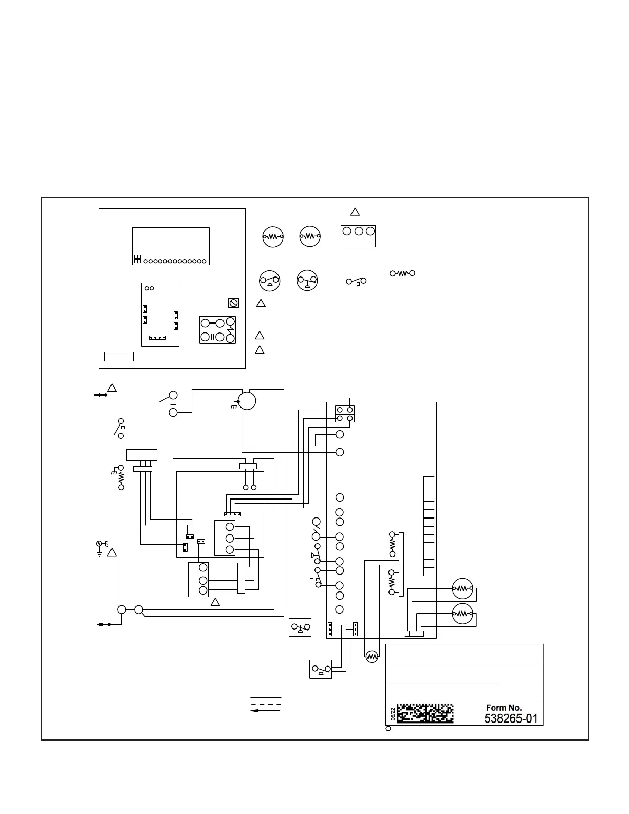
FIGURE 42. VAC Voltage Check
 Loading...


