Page 33
Table 6 continued
Outdoor Control Terminal Designations and Inputs / Outputs
WARNING - Electric Shock Hazard. Can cause injury or death. Unit must be grounded in accordance with national and
local codes. The 4 pins in P6 have the potential of transferring up to 250 volts to the unit cabinet ground.
Designator Description Input Output Common
P6 - Pin 1 Tx
Transmit data to inverter, connects to Rx of
inverter
Outdoor control
communication
transmit pin
– Pin 1 to pin 2 should read 4.5 to 5.55
VDC when not communicating
– Pin 3 to pin 2 should read 4.5 to 5.55
VDC when not communicating
– Pin 4 to pin 2 should read 4.5 to 5.5 VDC
NOTE - Communication signals switch o
and on rapidly. This may cause volt meter
readings to uctuate. This is normal. Com-
munication signals will switch between
this 5V and common (Pin 2).
P6 - Pin2
Inverter
Common
Inverter common
NOTE – This is a signal reference point
and not an earth ground.
Inverter common
P6 - Pin 3 Rx
Receive data from the inverter
Connects to Tx of inverter
Outdoor control
communication
receive pin
P6 - Pin 4 Inv 5V Inverter 5VDC volts Inverter 5VDC volts
DIS
Discharge Line temperature sensor - not
used (10K ohm resistor installed)
N/A N/A N/A
DIS
Discharge Line temperature sensor - not
used (10K ohm resistor installed)
N/A N/A N/A
AMB
Outdoor ambient temperature sensor
supply
N/A N/A N/A
AMB
Outdoor ambient temperature sensor
return
N/A N/A N/A
COIL
Outdoor coil temperature sensor - not used
(10K ohm resistor installed)
N/A N/A N/A
COIL
Outdoor coil temperature sensor - not used
(10K ohm resistor installed)
N/A N/A N/A
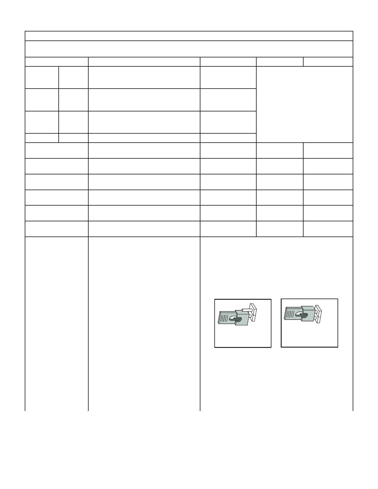
CHRG MODE
Charge Mode function. Can be used when
charging, checking charge, pump down or check-
ing unit operation. Unit will run at 100% capacity.
Conventional 24VAC thermostat
1. Install the Charge Mode jumper (before the Y1
demand)
2. Provide a Y1 demand to the EL23XCV
3. A blower demand must be provided to the in-
door unit for 100% of the cooling air volume.
4. Remove the charge mode jumper to end the
charge mode
S30 Communicating Thermostat
1. Install the Charge Mode jumper
2. Unit will start and run at 100% capacity and
communicate to the indoor unit to bring on the
blower at 100% of the cooling air volume.
4. Remove the charge mode jumper to end the
charge mode
NOTE - If the charge mode jumper is in the ON
position during power-up, it is ignored.
NOTE - If the charge mode is left in place, it will
be ignored after 60 minutes.
CHRG
Charge Mode
Disabled
Charge Mode
Enabled
MODE
CHRG
MODE

 Loading...

