Page 55
Verifying Liquid Pressure Transducer Operation
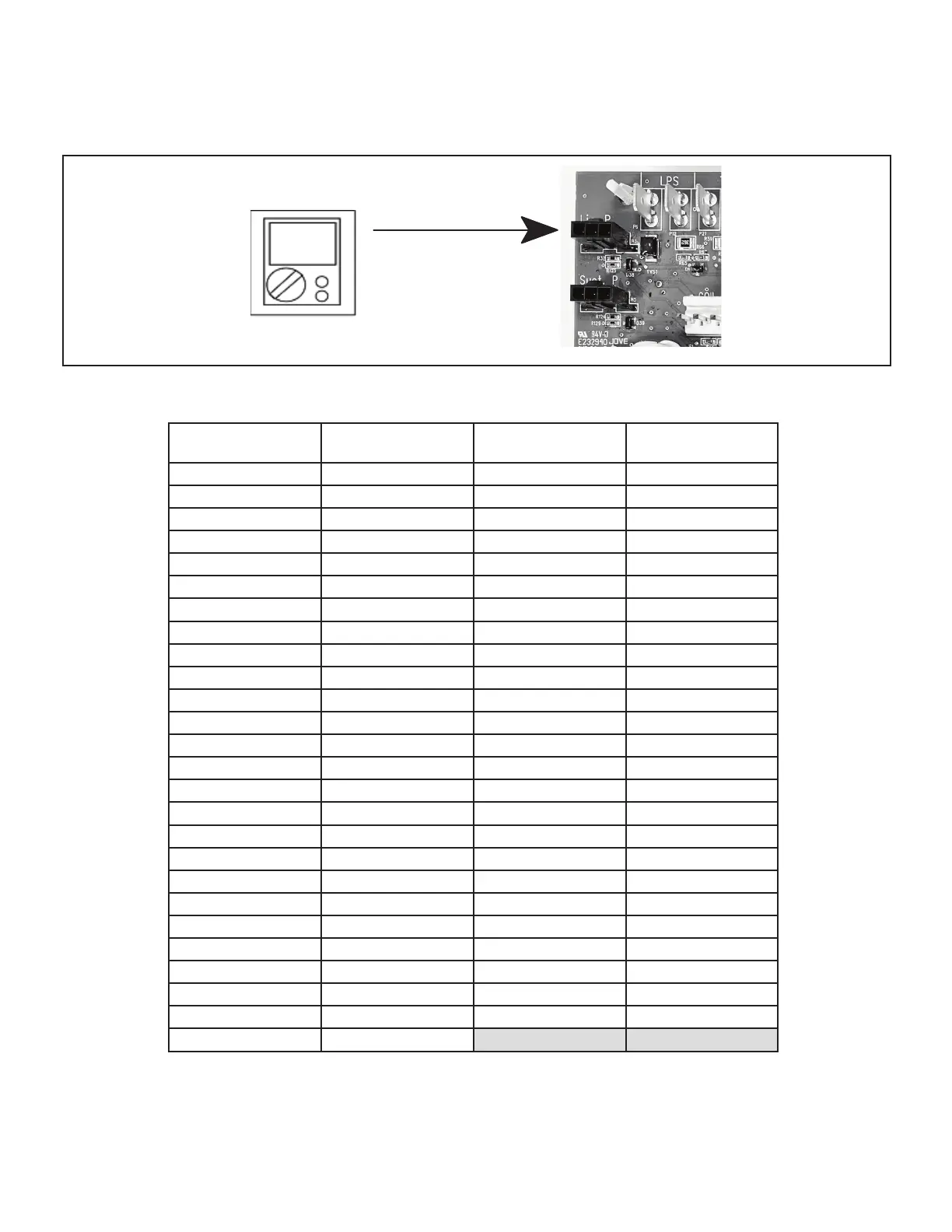
Using a multimeter set to VDC with the Liquid Pressure Transducer connected to the "Liq P" 3-pin connector on the control
board. Pin 1 (Red wire +5VDC) to Pin 3 (Black wire - GND) should read 5 VDC continuous. Pin 2 (Blue wire output from
transducer) to Pin 3 (Black - GND) should read 0.5 to 4.5 VDC and will vary depending on liquid~ pressure measured.
See Table 11.
VDC
FIGURE 27. Liquid Pressure Transducer Voltage
TABLE 11. Liquid Pressure Transducer Output Voltage
Liquid Pressure
(PSIG)
DC Voltage Output
(Pin 2 to Pin 3)
Liquid Pressure
(PSIG)
DC Voltage Output
(Pin 2 to Pin 3)
0 0.50 260 2.58
10 0.58 270 2.66
20 0.66 280 2.74
30 0.74 290 2.82
40 0.82 300 2.90
50 0.90 310 2.98
60 0.98 320 3.06
70 1.06 330 3.14
80 1.14 340 3.22
90 1.22 350 3.30
100 1.30 360 3.38
110 1.38 370 3.46
120 1.46 380 3.54
130 1.54 390 3.62
140 1.62 400 3.70
150 1.70 410 3.78
160 1.78 420 3.86
170 1.86 430 3.94
180 1.94 440 4.02
190 2.02 450 4.10
200 2.10 460 4.18
210 2.18 470 4.26
220 2.26 480 4.34
230 2.34 490 4.42
240 2.42 500 4.50
250 2.50

 Loading...

