Page 77
EL23XCV Charge Mode Operation with a S30 iComfort
Communicating Thermostat
Installing a jumper on the Charge Mode Pins will initiate
compressor operation and outdoor fan motor at 100% ca-
pacity and will provide a signal to the indoor unit to initiate
indoor blower operation at the maximum cooling air vol-
ume. To exit the charge mode, remove the Charge Mode
Jumper. The Charge Mode has a maximum time of 60
minutes and will automatically exit the charge mode after
60 minutes is the charge mode jumper is left in place.
EL23XCV Charge Mode Operation with a Convention-
al 24VAC Non-Communicating Thermostat
On applications with a conventional 24VAC non-commu-
nicating thermostat, the charge mode jumper must be in-
stalled on the Charge Mode Pins after providing a Y1 cool-
ing demand to the EL23XCV to initiate the Charge Mode.
A cooling blower demand must also be provided to initi-
ate blower operation on the cooling speed on the indoor
unit. The compressor and outdoor fan motor will operate
at 100% capacity. To exit the charging mode, remove the
Charge Mode Jumper and remove the Y1 Cooling de-
mand and indoor blower demand. The Charge Mode has
a maximum time of 60 minutes and will automatically exit
the charge mode after 60 minutes is the charge mode
jumper is left in place.
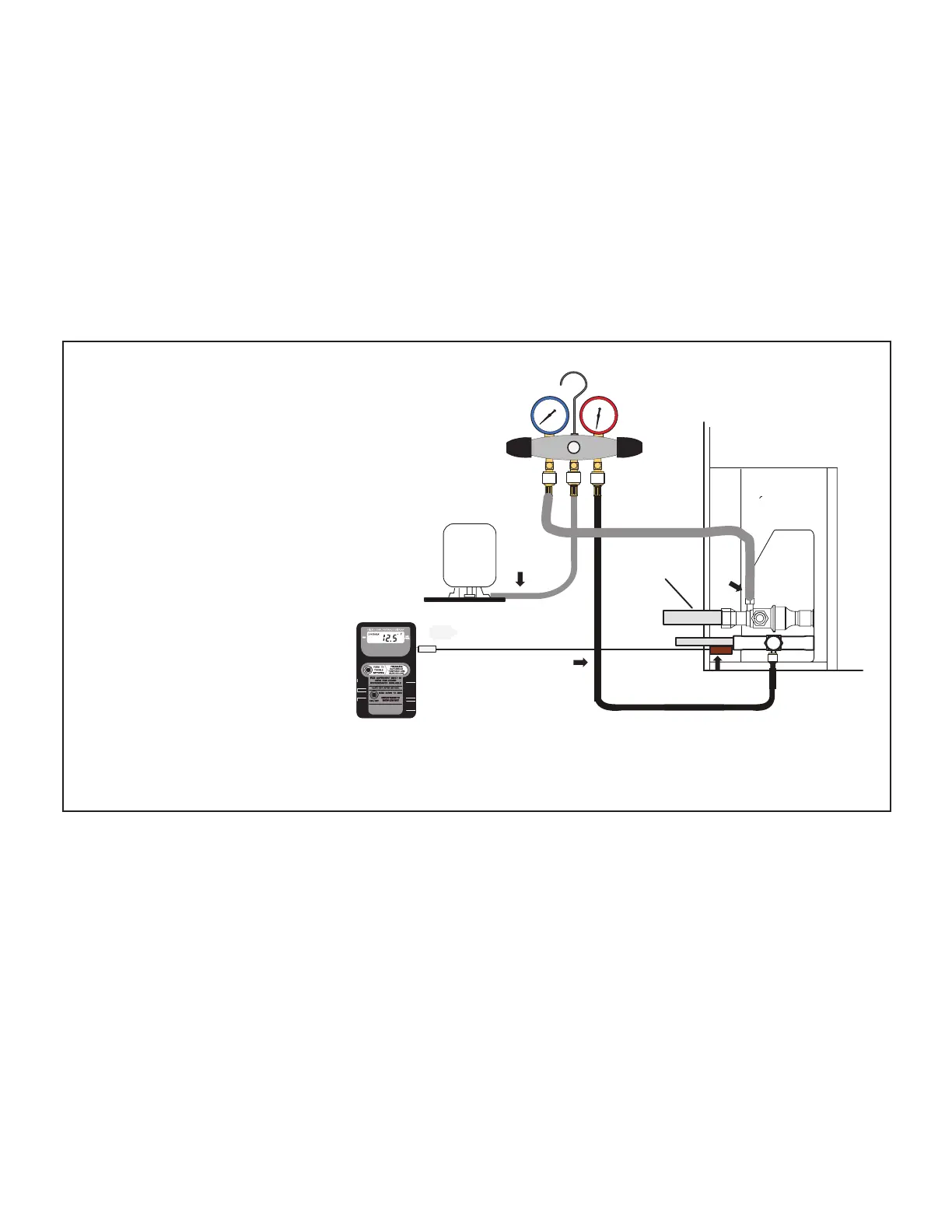
TO LIQUID
LINE SERVICE
PORT
TEMPERATURE
SENSOR
DIGITAL SCALE
REFRIGERANT TANK
TEMPERATURE SENSOR
(LIQUID LINE)
MANIFOLD GAUGE SET
A. CLOSE MANIFOLD GAUGE SET VALVES AND CONNECT THE CENTER HOSE TO A CYLINDER OF HFC-410A SET FOR LIQUID PHASE CHARGING.
B. CONNECT THE MANIFOLD GAUGE SET'S LOW PRESSURE SIDE TO THE SUCTION LINE SERVICE PORT.
C. CONNECT THE MANIFOLD GAUGE SET'S HIGH PRESSURE SIDE TO THE LIQUID LINE SERVICE PORT.
D. POSITION TEMPERATURE SENSOR ON LIQUID LINE NEAR LIQUID LINE SERVICE PORT.
OUTDOOR UNIT
CHARGE IN
LIQUID PHASE
CONNECTIONS FOR TESTING AND CHARGING
GAUGE SET
A
C
D
LOW
HIGH
B
SUCTION LINE
FIGURE 46. Gauge Set Connections

 Loading...

