Page 13
IMPORTANT
If any onboard link is cut by mistake, install a jump
er across the corresponding terminals on the low
voltage terminal strip. Do not replace control.
B- Indoor Blower
1. Secondary Limit Control (S21)
The secondary limit (S21) is located in the blower compart
ment. See figure 1. When excess heat is sensed in the blower
compartment, the limit will open. If the limit is open, the furnace
control energizes the supply air blower and closes the gas
valve. The limit automatically resets when unit temperature re
turns to normal. The switch must reset within three minutes or
the SureLight control will go into Watch guard for one hour.
The switch is factory set and cannot be adjusted.
EL280DFE units are equipped with a constant torque ECM
motor. It has a DC motor coupled to an electronic control
module both contained in the same motor housing. The mo
tor is programmed to provide constant torque at each of the
five selectable speed taps. Each tap requires 24 volts to en
ergize.
Input Voltage Requirements
The circuit is designed to be operated with AC voltage. To
enable a tap requires 12 to 33VAC. Expected current draw
will be less than 20mA.
Troubleshooting the Motor
Troubleshooting the motor is an easy process. Follow
steps below.
1- Shut off power to unit.
2- Remove input plugs P48 and P49 from motor. See
figure 8 for troubleshooting procedure.
If correct voltage is present in tests 1 and 2 and motor is not
operating properly, replace motor. The motor is not field re
pairable.
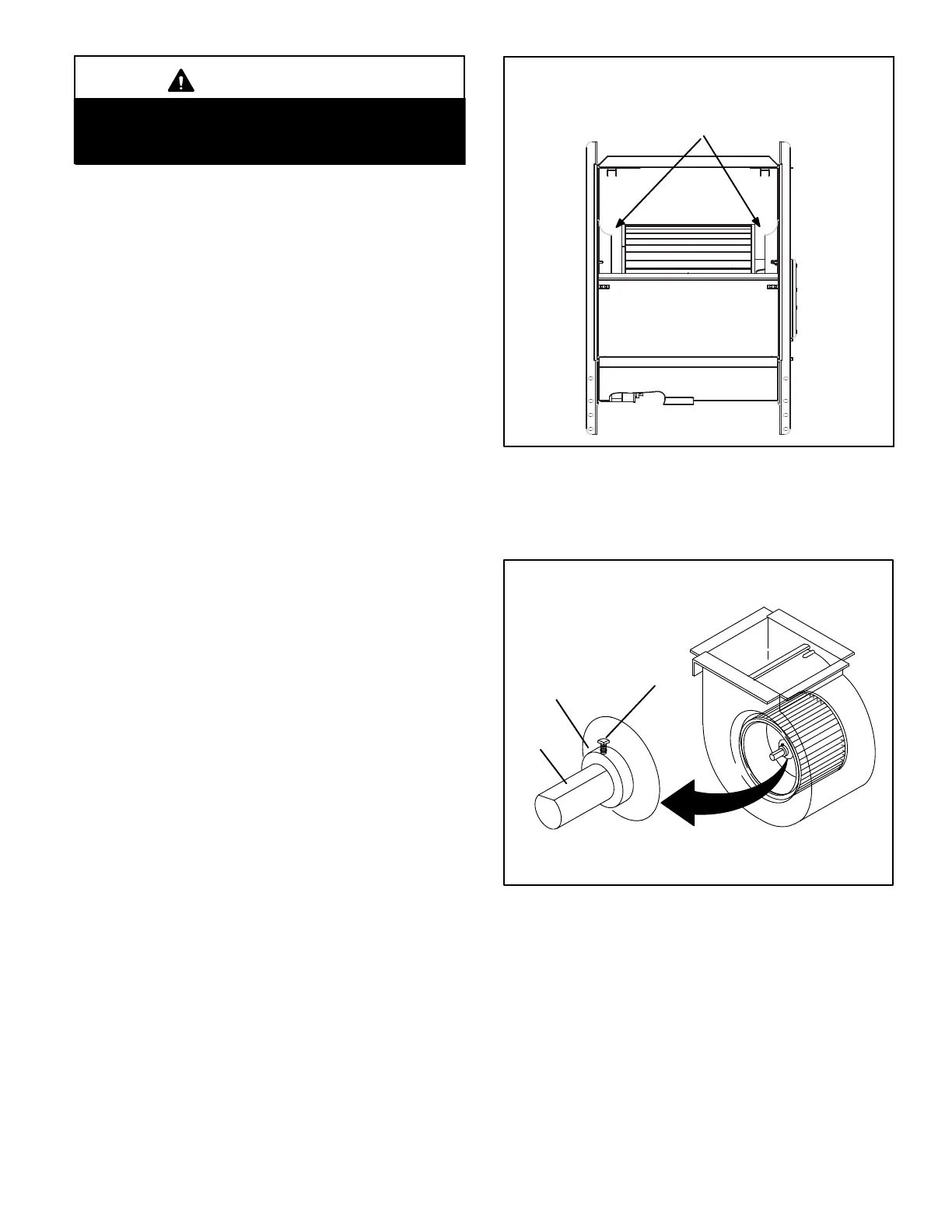
If replacing the indoor blower motor or blower wheel is nec
essary, placement is critical. The blower wheel must be cen
tered in the blower housing as shown in figure 6. When re
placing the indoor blower motor the set screw must be
aligned and tightened with the motor shaft as shown in figure
7.
FIGURE 6
Center Blower Wheel
in Blower Housing
BLOWER WHEEL REPLACEMENT
FIGURE 7
Set Screw
Housing Hub
ALIGN AND TIGHTEN SET SCREW WITH
FLAT SIDE OF MOTOR SHAFT
Motor
Shaft
 Loading...