Page 37
Electrical
WARNING
Electric Shock Hazard. Can cause injury or
death. Unit must be properly grounded in
accordance with national and local codes.
ELECTROSTATIC DISCHARGE (ESD)
Precautions and Procedures
CAUTION
Electrostatic discharge can aect electronic
components. Take precautions to neutralize
electrostatic charge by touching your hand
and tools to metal prior to handling the
control.
WARNING
Fire Hazard. Use of aluminum wire with this product may
result in a re, causing property damage, severe injury
or death. Use copper wire only with this product.
CAUTION
Failure to use properly sized wiring and circuit breaker
may result in property damage. Size wiring and circuit
breaker(s) per Product Specications bulletin (EHB) and
unit rating plate.
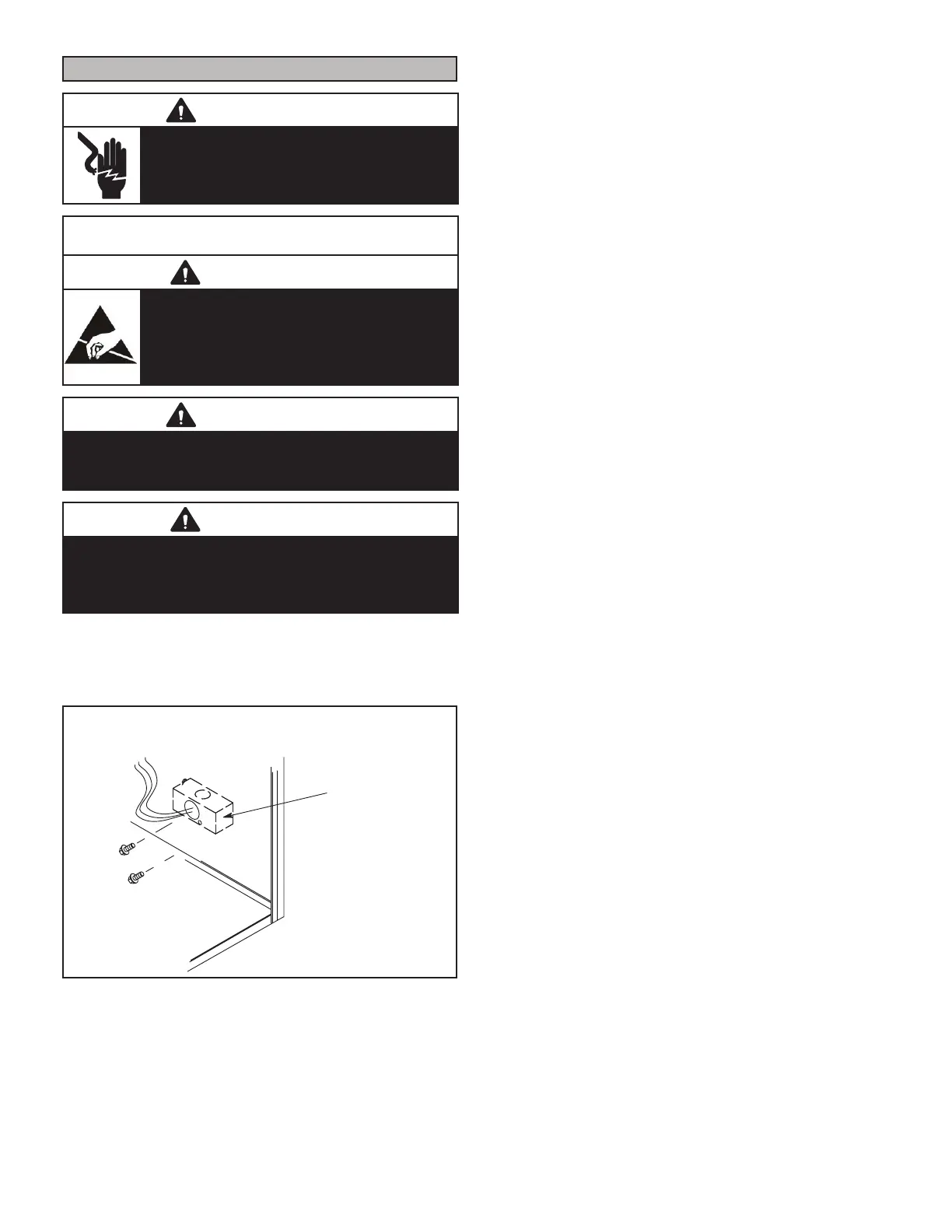
The unit is equipped with a eld make-up box. The make-
up box may be moved to the right side of the furnace to fa-
cilitate installation. Secure the excess wire to the existing
harness to protect it from damage.
MAKE-UP
BOX
OUTSIDE
CABINET
Right Side
(FIELD PROVIDED RIGHT SIDE)
FIGURE 57
Refer to FIGURE 59 and TABLE 15
EL296 Field Wiring Applications With Conventional Ther-
mostat15 for eld wiring, schematic wiring diagram and
troubleshooting.
The power supply wiring must meet Class I restrictions.
Protected by either a fuse or circuit breaker, select circuit
protection and wire size according to unit nameplate.
NOTE - Unit nameplate states maximum current draw.
Maximum Over-Current Protection allowed is 15 AMP.
Holes are on both sides of the furnace cabinet to facilitate
wiring.
Install a separate (properly sized) disconnect switch near
the furnace so that power can be turned o for servicing.
Before connecting the thermostat check to make sure
the wires will be long enough for servicing at a later date.
Make sure that thermostat wire is long enough to facilitate
future removal of blower for service.
Complete the wiring connections to the equipment Use
18-gauge wire or larger that is suitable for Class II rating
for thermostat connections.
Electrically ground the unit according to local codes or,
in the absence of local codes, according to the current
National Electric Code (ANSI/NFPA No. 70) for the USA
and current Canadian Electric Code part 1 (CSA standard
C22.1) for Canada. A green ground wire is provided in the
eld make-up box.
NOTE - The EL296DFE furnace contains electronic com-
ponents that are polarity sensitive. Make sure that the fur-
nace is wired correctly and is properly grounded.
Accessory Terminals
One line voltage “AAC” 1/4” spade terminal is provided
on the furnace integrated control. See FIGURE 58 for in-
tegrated control conguration. This terminal is energized
when the indoor blower is operating. Any accessory rated
up to one amp can be connected to this terminal with the
neutral leg of the circuit being connected to one of the pro-
vided neutral terminals. If an accessory rated at greater
than one amp is connected to this terminal, it is necessary
to use an external relay.
An unpowered, normally open (dry) set of contacts with
a 1/4” spade terminal “HUM” are provided for humidier
connections and may be connected to 24V or 120V. Any
humidier rated up to one amp can be connected to these
terminals. In 120V humidier applications the neutral leg of
the circuit can be connected to one of the provided neutral
terminals. This terminal is energized in the heating mode.
Install the room thermostat according to the instructions
provided with the thermostat. See FIGURE 59 for ther-
mostat designations. If the furnace is being matched with
a heat pump, refer to the FM21 installation instruction or
appropriate dual fuel thermostat instructions.
 Loading...