Page 13
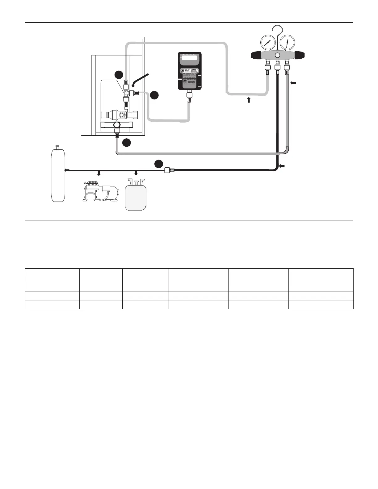
OUTDOOR UNIT
TO SUCTION
SERVICE VALVE
TO LIQUID
LINE SERVICE
VALVE
MICRON GAUGE
VACUUM PUMP
A34000 1/4 SAE
TEE WITH
SWIVEL
COUPLER
NITROGEN
50
MANIFOLD
GAUGE SET
HFC-410A
RECOMMEND MINIMUM
3/8” HOSE
A Connect low side of manifold gauge set with 1/4 SAE in-line tee to suction line
service valve
B Connect high side of manifold gauge set to liquid line service valve
C Connect micron gauge available connector on the 1/4 SAE in-line tee.
D Connect the vacuum pump (with vacuum gauge) to the center port of the
manifold gauge set. The center port line will be used later for both the
HFC-410A and nitrogen containers.
A
B
C
D
NOTE - Remove cores from service valves if not already done.
FIGURE 14
C-Charging
ELP units have a factory holding charge of 2 pounds of HFC-410A. Additional refrigerant will need to be added during
installation (table 4).
TABLE 4. Adding Refrigerant
Models
Total lbs –
Stage 1 with
25 ft line set
Liquid line
diameter
(inches)
Ounces adjustment
per ft of liquid line
Suction line diameter
(inches)
Ounces adjustment
per ft of suction line
ELP090S4S 23.25 5/8 1.5 1-1/8 0.2
ELP120S4S 32.5 5/8 1.5 1-1/8 0.2
To charge the system, use the following procedure:
1 - Measure actual length of liquid and vapor lines for
each circuit.
2 - Add refrigerant to each circuit based on measured
liquid and suction line lengths.
A - If the measured line length is greater than 25 feet,
add refrigerant (refer to table 2).
B - If the measured line length is less than 25 feet,
remove refrigerant (refer to table 2).
3 - Check normal operating pressures:
A - Connect a manifold gauge set to the service valves:
• Low pressure gauge to vapor valve service port
• High pressure gauge to liquid valve service port
B - Operate the system until pressures and
temperatures stabilize (5 minutes minimum).
C - Use a thermometer to measure the outdoor ambient
temperature.
D - If the outdoor temperature is greater than 65ºF (18ºC):
• Apply the outdoor ambient temperature to tables
4 or 5 to determine normal operating pressures.
Compare the normal operating pressures to the
pressures obtained from the connected gauges. If
liquid pressure is high, remove refrigerant from the
system. If liquid pressure is low, add refrigerant to
the system.
• Add or remove charge in increments.
• Allow the system to stabilize at least 5 minutes each
time refrigerant is added or removed.
• Minor variations in these pressures may be expect-
ed due to dierences in installations. Signicant dif-
ferences could mean that the system is not properly
charged or that a problem exists with some compo-
nent in the system.
 Loading...