Page 9
TABLE 2
REFRIGERANT LINE SIZES
ELP Unit Liquid Line Vapor Line
090 5/8" (16mm) 1-1/8" (29mm)
120 5/8" (16mm) 1-1/8" (29mm)
B-Service Valves
When servicing or repairing HVAC components, ensure
caps and fasteners are appropriately tightened. Table 3
lists torque values for typical service and repair items.
TABLE 3
Torque Requirements
Part Recommended Torque
Service valve cap 8 ft.-lb. 11 NM
Sheet metal screws 16 in.-lb. 2 NM
Machine screws #10 28 in.-lb. 3 NM
Compressor bolts 90 in.-lb. 10 NM
Gauge port seal cap 8 ft.-lb. 11 NM
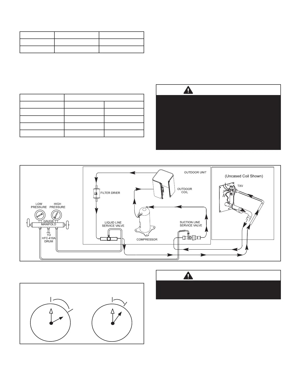
USING MANIFOLD GAUGE SETS
When checking the system charge, use a manifold gauge
set that features low-loss anti-blow back ttings. See g-
ure 9 for a typical manifold gauge connection setup.
Manifold gauge sets used with HFC-410A refrigerant sys-
tems must be capable of handling the higher system oper-
ating pressures. The gauges should be rated for use with
pressures of 0 - 800 on the high side and a low side of 30"
vacuum to 250 psi with dampened speed to 500 psi.
Gauge hoses must be rated for use at up to 800 psi of
pressure with a 4000 psi burst rating.
OPERATING SERVICE VALVES
The liquid and vapor line service valves are typically used
for removing refrigerant, ushing, leak testing, evacuating,
checking charge and charging.
IMPORTANT
Only use Allen wrenches of sucient hardness (50Rc
- Rockwell Harness Scale minimum). Fully insert the
wrench into the valve stem recess.
Service valve stems are factory-torqued (from 9 ft-lbs
for small valves, to 25 ft-lbs for large valves) to prevent
refrigerant loss during shipping and handling. Using an
Allen wrench rated at less than 50Rc risks rounding
or breaking o the wrench, or stripping the valve stem
recess.
FIGURE 9
Each valve is equipped with a service port which has a
factory-installed valve stem.
1
2
3
4
5
7
8
9
10
11
12
1/6 TURN
1
2
3
4
5
7
8
9
10
11
12
1/12 TURN
FIGURE 10
IMPORTANT
To prevent stripping of the various caps used, the
appropriately sized wrench should be used and tted
snugly over the cap before tightening.
To Access Angle-Type Service Port:
A service port cap protects the service port core from con-
tamination and serves as the primary leak seal.
1 - Remove service port cap with an appropriately
sized wrench.
2 - Connect gauge to the service port.
 Loading...