FLEXYII_WSHP-IOM-1307-E - 45 -
2
nd
method when adjusting the pulley :
-Close the pulley fully and count the number of turns
from fully closed position. Using table_1 determine the
motor pulley actual diameter.
-Record the fix fan pulley diameter.(DF)
-Determine the fan speed using the following formulae:
Where: rpm
MOTOR
:from the motor plate or table_2
D
M
: from table_1
D
F
: from machine
Once the pulleys are adjusted and the belt checked and
tensioned, start the fan motor and record the Amps and
Voltage between the phases:
Using the measured data and table_2
-Theoretical mechanical power at the fan shaft:
P
meca fan
= P
meca Motor
x η
Transmission
P
meca fan
= P
elec
x η
meca motor
x η
Transmission
P
meca fan
= V x I x √3 x cosϕ x η
meca motor
x η
Transmission
This formula can be approximated in this way
P
meca fan
= V x I x 1.73 x 0.78 x 0.87 x 0.9
With the fan “rpm” and the mechanical power at the fan
shaft an operating point and the supplied airflow can be
estimated using the fan curves.
CHECKING AIRFLOW AND ESP
Using the fan curves on page 36 to 40, the airflow, the total
pressure available (P
TOT
) and the corresponding dynamic
pressure (Pd) can now be estimated, for a specific
operating point;
The next step consists in estimating the pressure losses
across the unit.
This can be achieved using the “dirty filter pressure sensor”
and the accessories pressure drop table: table_3
Also the pressure drop due to the duct inlet into the roof-top
unit can be taken as 20 to 30 Pa.
∆P
INT
= ∆P
filter + coil
+ ∆P
Inlet
+ ∆P
Options
Using the results from above, the external static pressure
(ESP) can then be estimated:
ESP = P
TOT
- Pd - ∆P
INT
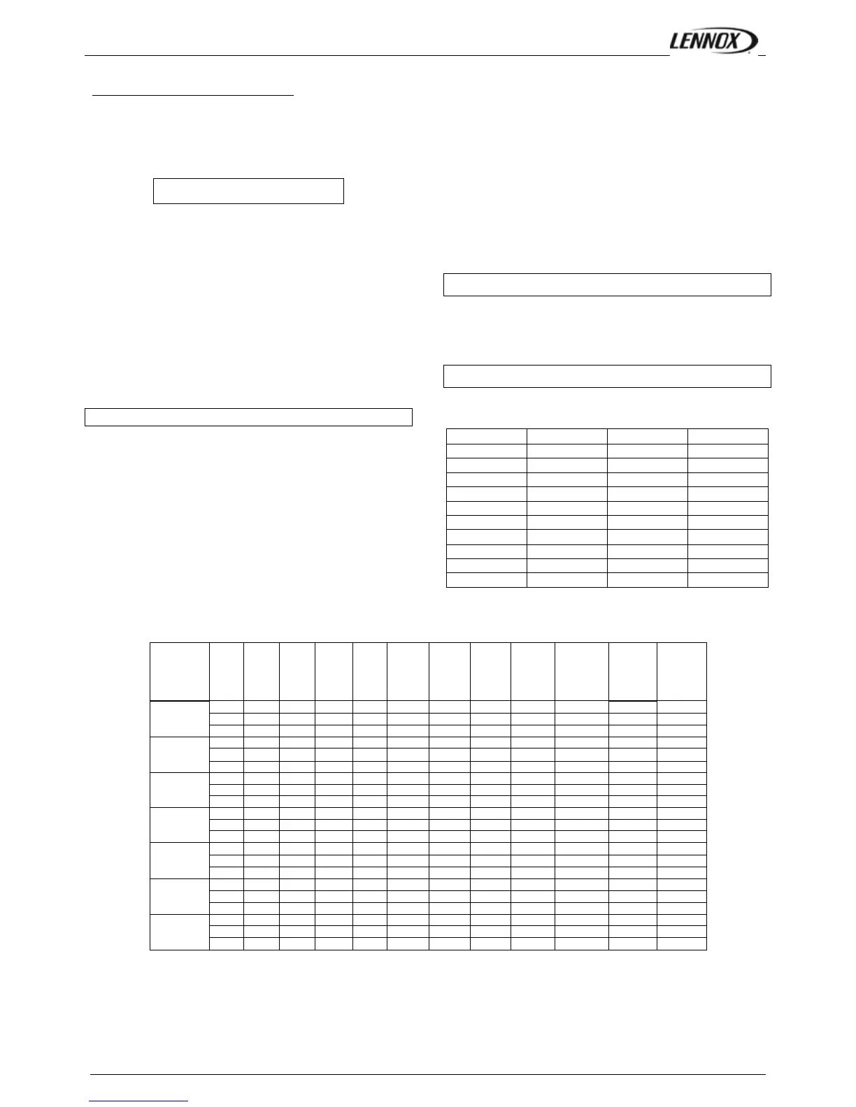
Table_ 2 Motor information
 Loading...