VENTILATION : AIRFLOW BALANCING
FLEXYII_WSHP-IOM-0909-E Page 52
EXAMPLE
The unit used for this example is a FGM170ND with standard supply and return airflow configuration. It is also fitted with an
economiser and an electric heater type H.
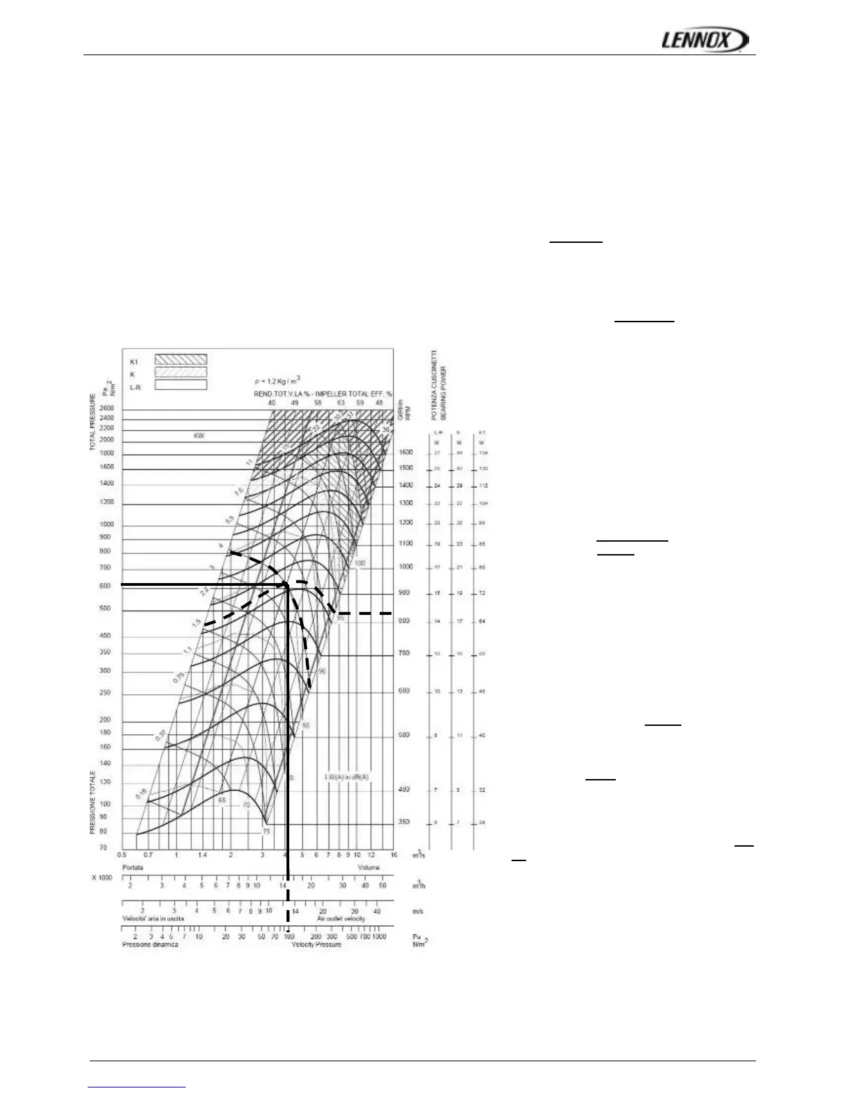
It is fitted with 2 ADH450 L fans which curve is shown on page 36 and 2x 5.5 kW motors..
- Motor rpm: 1447 rpm
- cosϕ = 0.83
- Voltage = 400V
- Current = 9.00A (per fan)
P
mech fan
= V x I x √3 x cosϕ x η
mech motor
x η
Transmission
= 400 x 9.00 x √3 x 0.83 x 0.86 x 0.9 = 4.00kW
The unit is also fitted with 2 transmission kits 3.
- Fixed Fan pulley: 200mm
- Motor adjustable pulley type “8550” opened 4 turns from fully closed or measured distance between pulley end plates is
29.1mm: from table_1 it can be determined that each motor pulley has a diameter of 114.2mm
rpm
FAN
= rpm
MOTOR
x D
M
/ D
F
= 1447 x 114.2 / 200 = 826 rpm
Using the fan curve, the operating point can
be located.
In order to facilitate the calculation, you
won’t make any mistake by considering
that the external static pressure available is
the one calculated with one fan providing
the half of the nominal flow (here
15000m3/h).
It can be determined that the fan is providing
approximately 15000 m3/h
with a total
pressure P
TOT
= 630 Pa
The pressure losses in the unit are the sum of
all pressure drops across the different parts of
a unit:
- Coil and filter (measured) = 89 Pa
- Inlet into the unit = 50 Pa
- Options = 16 Pa for economiser and 15
Pa for electric heater H
∆P = 89 + 16 + 15 +50 = 170 Pa
The dynamic pressure at 15000m
3
/h is given
at the bottom of the fan curve.
Pd = 81 Pa
The external static pressure available is
therefore
ESP = P
TOT
- Pd - ∆P
INT
=630 - 91 - 170 = 369
Pa
826rpm
630Pa
 Loading...