WATER CONDENSING
FLEXYII_WSHP-IOM-0909-E Page 20
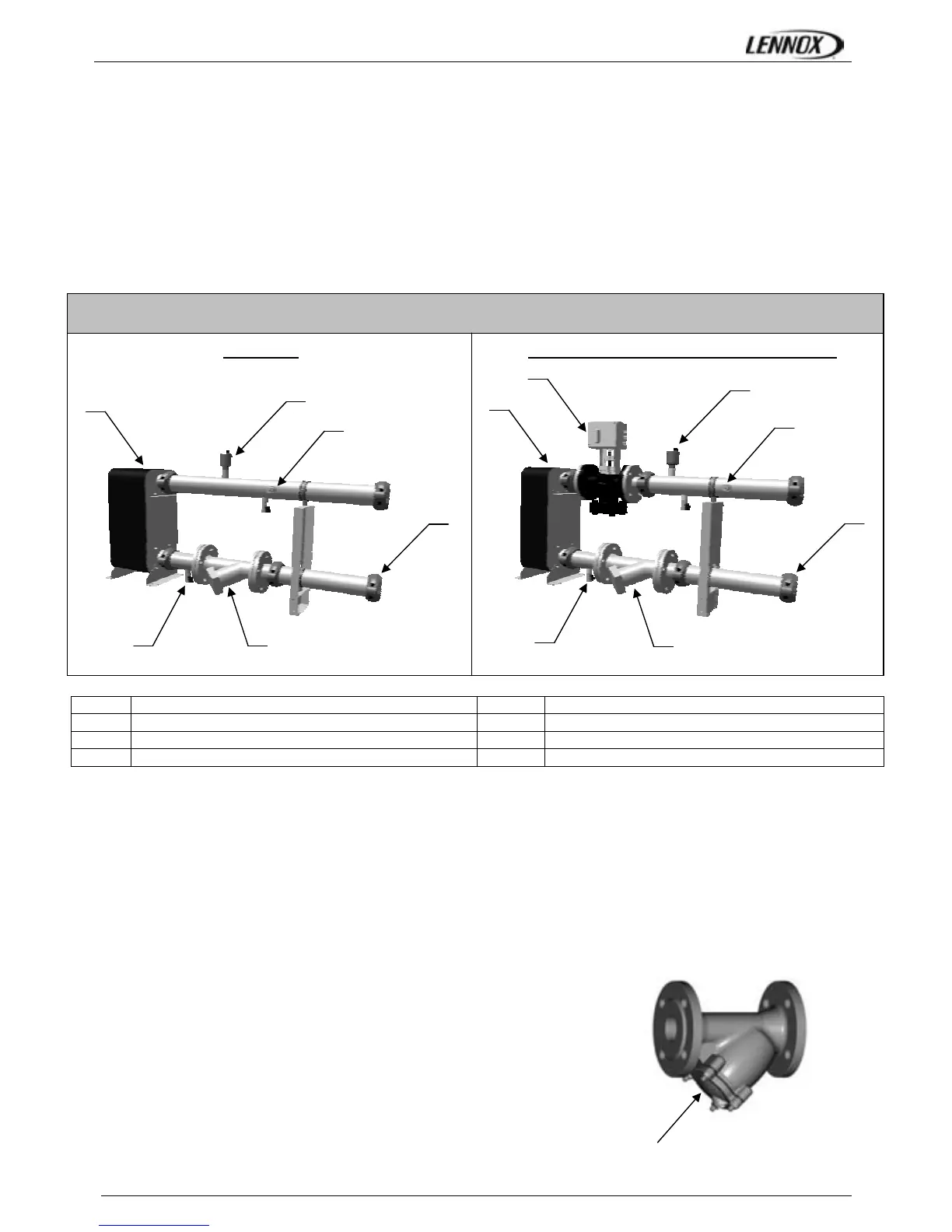
WATER LOOP CONFIGURATION (FOR WATER SOURCE HEAT PUMP)
Figures below show the 2 water configurations.
Figure 1 indicates all components used as standard :
• the electronic water flow switch,
• the water filter,
• the pressure taps and drain valves,
• the automatic airvent,
The second figure shows rooftop water loop with Low Water Loop Temperature option.
LOW WATER LOOP TEMPERATURE (OPTION)
In order to operate with low water inlet temperature in cooling mode (ie: ground source water loops) it is necessary to control
the water flow rate in the heat exchanger to maintain a minimum condensing pressure in the refrigeration circuit.
In cooling mode the climatic 50 will control the water flow rate in the condenser by monitoring the condensing pressure and by
closing the water flow valve accordingly by a 0-10 Volts signal.
This option offers a second opportunity: give the possibility to close the rooftop water loop when compressors are stopped.
WATER FILTER REPLACEMENT (ONLY FOR WATER SOURCE HEAT PUMP)
It is important that units are serviced regularly by a qualified technician, at least
once every year or every 1000 hours of operation.
CAUTION: The water circuit may be pressurised. Observe the usual
precautions when depressurising the circuit before opening it. Failure to
observe these rules could lead to accidents and cause injury to service
personal.
1
All Victaulic Connections
5
Pressure Taps and drain Valve
2
Inlet Water Filter
6
Stainless steel Exchanger
3
Automatic Air Vent
7
ElectroValve (HP control option)
4
Electronic Flow Switch
2
1
3
4
5
6
1
2
3
4
5
6
7
Low Water Loop Temperature Option
Hydraulic Data
Standard
Access for cartridge cleaning
Figure 1 Figure 2
 Loading...