EasyManua.ls Logo

Lennox G23Q3-100 User Manual

Lennox G23Q3-100
52 pages
To Next Page IconTo Next Page
Page #1 background imageLoading...
Page #1 background image
Page 1
ã 1998 Lennox Industries Inc.
L
i
t
h
o
U
.
S
.
A
.
Corp. 9814-L8
G23(X)
Service Literature
Revised 08-2001
G23(X) SERIES UNITS
G23(X) series units are mid-efficiency upflow gas fur-
naces manufactured with Duralokt aluminized steel
clamshell type heat exchangers. G23(X) units are avail-
able in heating capacities of 50,000 to 150,000 Btuh and
cooling applications up to 6 tons. Refer to Engineering
Handbook for proper sizing.
Units are factory equipped for use with natural gas. A kit is
available for conversion to LPG operation. G23(X)-1, -2, -3
and-4modelunitsuseelectronic (intermittentpilot)ignition.
G23(X)-5 and -6 model units feature the Lennox Sur-
eLightT silicon nitride ignition system. All units meet the
California Nitrogen Oxides (NO
x
) Standards and California
Seasonal Efficiency requirements with the installation of
flame baffles. All units use a redundant gas valve to assure
safety shut-off as required by A.G.A. or C.G.A.
Information contained in this manual is intended for use by
qualified service technicians only. All specifications are
subject to change. Procedures outlined in this manual are
presented as a recommendation only and do not super-
sede or replace local or state codes. In the absence of lo-
cal or state codes, the guidelines and procedures outlined
in this manual (except where noted) are recommended
only.
SPECIFICATIONS
Model No. G23Q2(X)-50 G23Q3(X)-50 G23Q2/3(X)-75 G23Q4/5(X)-75 G23Q3(X)-100
Input Btuh (kW) 50,000 (14.7) 75,000 (22.0) 100,000 (29.3)
Output Btuh (kW) 40,000 (11.7) 61,000 (17.8) 80,000 (23.4)
lA.F.U.E. 80.7% 80.8% 80.4% 80.1%
California Seasonal Efficiency 75.5% 75.6% 76.9% 74.2% 76.6%
Flue size connection diameter in. (mm) round 3 (76) 4 (102)
Temperature rise range _F (_C) 30-60 (17-33) 35-65 (19-36) 20-50 (11-28) 45-75 (25-42)
High static certified by A.G.A. in wg. (Pa) .50 (125)
G
a
s
P
i
p
i
n
g
S
i
z
e
I
.
P
.
S
.
in. 1/2
G
a
s
P
i
p
i
n
g
S
i
z
e
I
.
P
.
S
.
Natural or LPG/propane
mm 12.7
B
l
o
w
e
r
w
h
e
e
l
n
o
m
i
n
a
l
in. 10 x 7 10 x 8 11-1/2 x 9 10 x 8
B
l
o
w
e
r
w
h
e
e
l
n
o
m
i
n
a
l
diameter x width
mm 254 x 178 254 x 203 292 x 229 254 x 203
Blower motor output hp (W) 1/5 (149) 1/3 (249) 3/4 (560) 1/3 (249)
N
o
m
i
n
a
l
c
o
o
l
i
n
g
Tons 1 to 2 1 to 3 3-1/2 to 5 1 to 3
N
o
m
i
n
a
l
c
o
o
l
i
n
g
that can be added
kW 3.5 to 7.0 3.5 to 10.6 12.3 to 17.6 3.5 to 10.6
Shipping weight lbs. (kg) 1 package 135 (61) 140 (64) 146 (66) 186 (84) 159 (72)
Electrical characteristics 120 volts 60 hertz 1 phase (all models) (less than 12 amps)
lAnnual Fuel Utilization Efficiency based on U.S. DOE test procedures and FTC labeling regulations. Isolated combustion system rating for non-weatherized furnaces.
}Cleanable polyurethane frame type filter.

Table of Contents

Other manuals for Lennox G23Q3-100

Question and Answer IconNeed help?

Do you have a question about the Lennox G23Q3-100 and is the answer not in the manual?

Lennox G23Q3-100 Specifications

General IconGeneral
BrandLennox
ModelG23Q3-100
CategoryFurnace
LanguageEnglish

Summary

G23(X) Furnace Overview and Specifications

Specifications

Detailed technical data for G23(X) furnace models, including performance and dimensions.

Unit Components and Installation

Optional Accessories

Available kits and parts to enhance furnace functionality and installation.

Unit Components Orientation

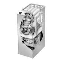
Visual guide illustrating the location of major internal furnace components.

Control Box and Ignition Systems

Details on electrical controls, transformer, and ignition systems for furnace operation.

Gas Valve and Combustion Air Blower

Description of gas valve types and the function of the combustion air blower switch.

Installation, Venting, and Operation

Placement and Installation Requirements

Guidelines for ensuring adequate fresh air for combustion and proper furnace placement.

Flue Venting Requirements

Standards and guidelines for safely and effectively venting the furnace flue.

Heating Start-Up and Gas Checks

Step-by-step procedures for safe furnace start-up and essential gas system checks.

Typical Operating Characteristics

Information on blower operation, temperature rise, and static pressure for performance monitoring.

Maintenance, Wiring, and Sequences

Maintenance Procedures

Routine maintenance tasks for filters and heat exchanger to ensure optimal furnace performance.

Field Wiring Diagram

Wiring schematic illustrating connections to thermostat, control box, and other components.

Heating Sequence of Operation

Detailed operational sequence for the furnace heating mode, covering normal and abnormal conditions.

Cooling Sequence of Operation

Operational sequence for the furnace cooling mode, detailing normal and abnormal conditions.

Troubleshooting Guide

BCC Blower Control Troubleshooting

Step-by-step guide to diagnose and resolve issues with the BCC blower control.

Ignition Control Troubleshooting

Diagnostic flowcharts for identifying and fixing ignition system failures.

SureLight Troubleshooting

Guide to diagnose and resolve common problems with the SureLight ignition system.

Heating Mode Failure Problems

Troubleshooting steps for addressing unit failures specifically in heating mode.

Related product manuals