Page 18
F- Proper Gas Flow
Furnace should operate at least 5 minutes before checkĆ
ing gas flow. Determine time in seconds for two revoluĆ
tions of gas through the meter. (Two revolutions assures
a more accurate time.) Divide by two and compare to time
in table 10 below. Adjust manifold pressure on gas valve
to match time needed.
NOTE- To obtain accurate reading, shut off all other
gas appliances connected to meter.
TABLE 10
GAS METER CLOCKING CHART
Seconds for One Revolution
G24M
Natural LP
Unit
1 cu ft
Dial
2 cu ft
Dial
1 cu ft
Dial
2 cu ft
DIAL
-45 80 160 200 400
-60 60 120 150 300
-75 48 96 120 240
-100 36 72 90 180
-120 30 60 75 150
-140 26 52 64 128
Natural-1000 btu/cu ft LP-2500 btu/cu ft
NOTE- To obtain accurate reading, shut off all other
gas appliances connected to meter.
G-High Altitude Derate
NOTE-In Canada, certification for installation at altiĆ
tudes over 4500 ft. (1372m) above sea level is the jurisĆ
diction of the local authorities.
G24M-1 through -9 Models
This unit does not require gas pressure adjustment, or
pressure switch change when operating at elevations of 0
to 7500 ft. (0 to 2248m). Check gas line pressure with unit
firing. The minimum pressure as shown on the nameplate
for natural and propane gases must be maintained. No oriĆ
fice change is required.
NOTE-This is the only permissible field derate for this
appliance.
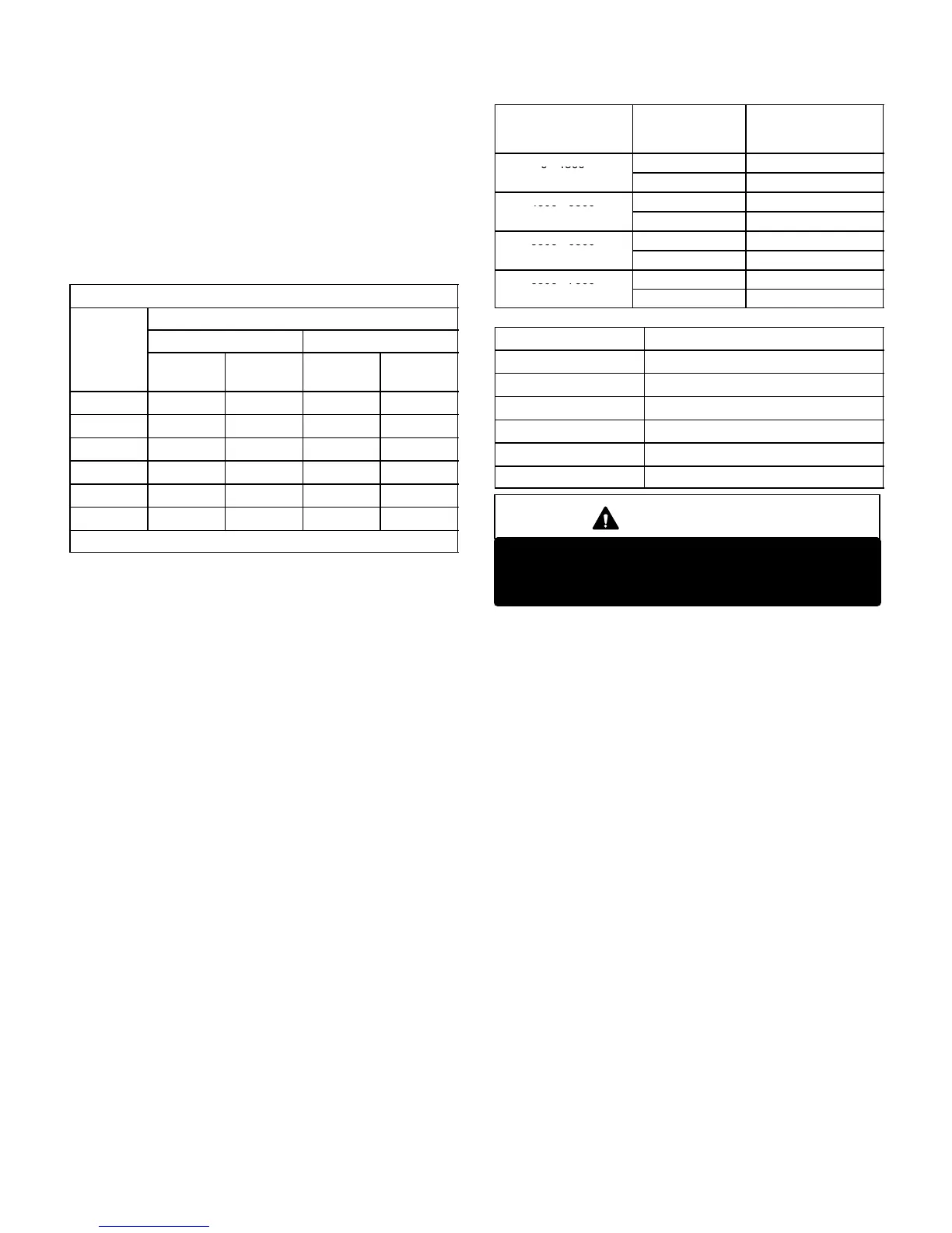
G24M-10 and -11 Models
Table 11 shows manifold pressure settings for installations
at different altitudes. Refer to table 12 for pressure switch
replacement for models at elevations of 4500 feet (1372m)
and greater.
TABLE 11
ALTITUDE
feet (m)
GAS FUEL
MANIFOLD
PRESSURE
in. W.C. (kPa)
0 - 4500
Natural 3.5 (0.87)
(0 - 1372)
Propane/LP 9.5 (2.36)
4500 - 5500
Natural 3.4 (0.86)
(1372 - 1676)
Propane/LP 9.2 (2.29)
5500 - 6500
Natural 3.3 (0.82)
(1676 - 1981)
Propane/LP 8.9 (2.21)
6500 - 7500
Natural 3.2 (0.80)
(1372 - 2286)
Propane/LP 8.6 (2.14)
TABLE 12
Unit Model Pressure Switch Part Number
G24M-45 No Change
G24M-60 No Change
G24M-75 88J8001
G24M-100 18L2401
G24M-120 18L2401
G24M-140 No Change
IMPORTANT
For safety, shut unit off and remove manometer as
soon as an accurate reading has been obtained.
Take care to replace pressure tap plug.
H-Flame Signal
A microamp DC meter is needed to check the flame signal
on the primary ignition control.
Flame (microamp) signal is an electrical current which
passes from the furnace control through the sensor elecĆ
trode during unit operation. Current passes from the senĆ
sor through the flame to ground to complete a safety cirĆ
cuit.
To Measure Flame Signal:
1 - Place meter in series between furnace control and
sensor wire. Connect the positive (+) lead of meter to
the ignition control sensor connection and the negaĆ
tive (-) lead of the meter to the sensor wire. See figure
21.
2 - Set thermostat for a heating demand and check flame
signal with unit operating. For G24M series with a RAM
control, a reading of 1 to 5 microamps DC should occur.
The furnace control must see at least 1.0 microamps in
order to keep the gas valve energized. G24M units with
the SureLight control should read 0.7 microamps or
more.

 Loading...


