3DJH
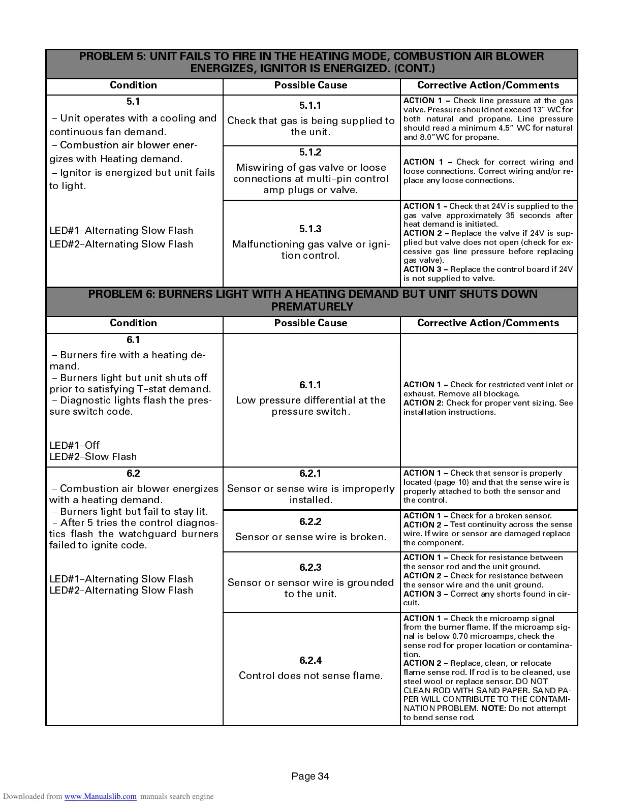
PROBLEM 5: UNIT FAILS TO FIRE IN THE HEATING MODE, COMBUSTION AIR BLOWER
ENERGIZES, IGNITOR IS ENERGIZED. (CONT.)
Condition Possible Cause Corrective Action/Comments
5.1
-- Unit operates with a cooling and
continuous fan demand.
Combustion air blower ener
5.1.1
Check that gas is being supplied to
the unit.
ACTION 1 --
Check line pressure at the gas
valve.Pressure should not exceed 13WC for
both natural and propane. Line pressure
should read a minimum 4.5 WC for natural
and 8.0WC for propane.
--
om
ust
on a
r
ower ener-
gizes with Heating demand.
--
Ignitor is energized but unit fails
to light.
5.1.2
Miswiring of gas valve or loose
connections at multi--pin control
amp plugs or valve.
ACTION 1 --
Check for correct wiring and
loose connections. Correct wiring and/or re-
place any loose connections.
LED#1--Alternating Slow Flash
LED#2--Alternating Slow Flash
5.1.3
Malfunctioning gas valve or igni-
tion control.
ACTION 1 --
Check that 24V is supplied to the
gas valve approximately 35 seconds after
heat demand is initiated.
ACTION 2 --
Replace the valve if 24V is sup-
plied but valve does not open (check for ex-
cessive gas line pressure before replacing
gas valve).
ACTION 3 --
Replace the control board if 24V
is not supplied to valve.
PROBLEM 6: BURNERS LIGHT WITH A HEATING DEMAND BUT UNIT SHUTS DOWN
PREMATURELY
Condition Possible Cause Corrective Action/Comments
6.1
-- Burners fire with a heating de-
mand.
-- Burners light but unit shuts off
prior to satisfying T--stat demand.
-- Diagnostic lights flash the pres-
sure switch code.
LED#1--Off
LED#2--Slow Flash
6.1.1
Low pressure differential at the
pressure switch.
ACTION 1 --
Check for restricted vent inlet or
exhaust. Remove all blockage.
ACTION 2:
Check for proper vent sizing. See
installation instructions.
6.2
-- Combustion air blower energizes
with a heating demand.
6.2.1
Sensor or sense wire is improperly
installed.
ACTION 1 --
Check that sensor is properly
located (page 10) and that the sense wire is
properly attached to both the sensor and
the control.
-- Burners light but fail to stay lit.
-- After 5 tries the control diagnos-
tics flash the watchguard burners
failed to ignite code.
6.2.2
Sensor or sense wire is broken.
ACTION 1 --
Check for a broken sensor.
ACTION 2 --
Test continuity across the sense
wire. If wire or sensor are damaged replace
the component.
LED#1--Alternating Slow Flash
LED#2--Alternating Slow Flash
6.2.3
Sensor or sensor wire is grounded
to the unit.
ACTION 1 --
Check for resistance between
the sensor rod and the unit ground.
ACTION 2 --
Check for resistance between
the sensor wire and the unit ground.
ACTION 3 --
Correct any shorts found in cir-
cuit.
6.2.4
Control does not sense flame.
ACTION 1 --
Check the microamp signal
from the burner flame. If the microamp sig-
nal is below 0.70 microamps, check the
sense rod for proper location or contamina-
tion.
ACTION 2 --
Replace, clean, or relocate
flame sense rod. If rod is to be cleaned, use
steel wool or replace sensor. DO NOT
CLEAN ROD WITH SAND PAPER. SAND PA-
PER WILL CONTRIBUTE TO THE CONTAMI-
NATION PROBLEM.
NOTE:
Do not attempt
to bend sense rod.
 Loading...


