Page 26
D-Late Model G24M Series With SureLight Ignition Control
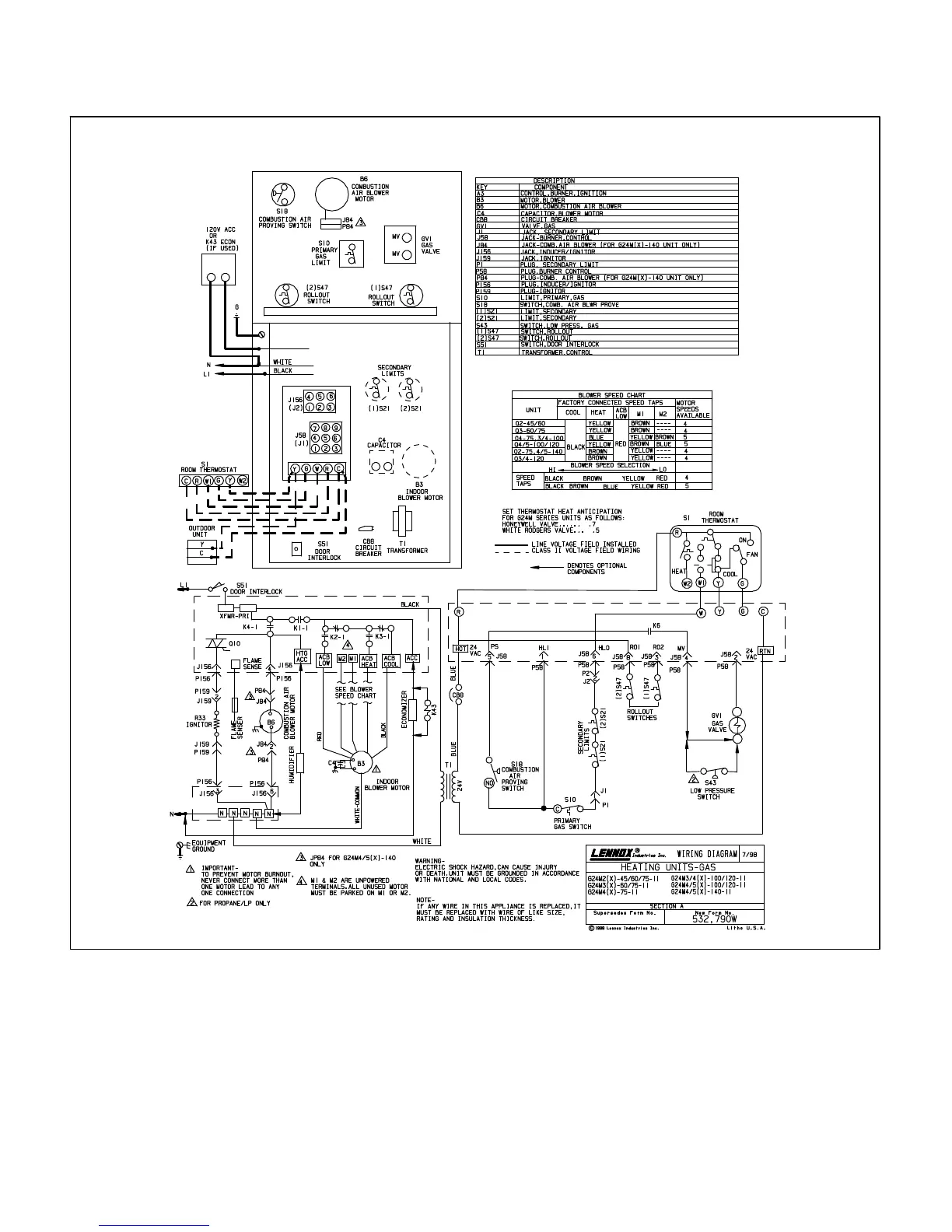
TYPICAL G24M DIAGRAM
(-11 MODEL SHOWN)
1 - When there is a call for heat, W1 of the thermostat ener-
gizes W of the furnace control with 24VAC.
2 - S10 primary limit switch and S47 rollout switch are closed.
Call for heat can continue.
3 - SureLight control energizes combustion air blower B6.
Combustion air blower runs until S18 combustion air prove
switch closes (switch must close within 2-1/2 minutes or
control goes into 5 minute Watchguard Pressure Switch
delay). Once S18 closes, a 15-second pre-purge follows.
4 - SureLight control energizes ignitor. A 20-second warm-up
period begins.
5 - Gas valve opens for a 4-second trial for ignition. Ignitor
stays energized the first second of trial. (Board 97L48 only:
ignitor energized during trial or until flame is sensed.
6 - Flame is sensed, gas valve remains open for the heat call.
7 - After 45-second delay, SureLight control energizes indoor
blower B3.
8 - Whenheatdemandissatisfied,W1oftheindoorthermostat
de-energizes W of the SureLight control which de-ener-
gizes the gas valve. Combustion air blower B6 continues a
5-second post-purge period, and indoor blower B3 com-
pletes a selected OFF time delay.

 Loading...


