Page 12
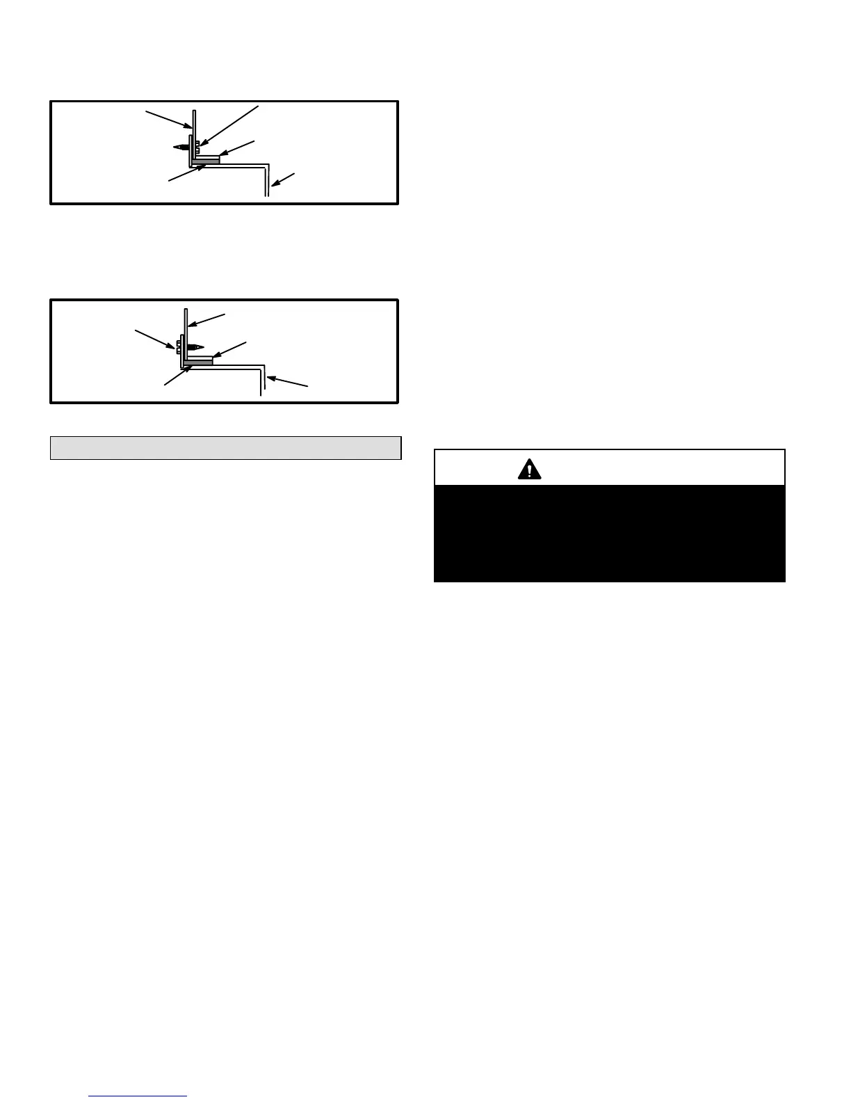
3 - In all cases, secure the plenum to the top flanges of the
furnace using sheet metal screws. See figure 13.
SECURE
HEMMED EDGE
PLENUM
CABINET
SIDE PANEL
FIBERGLASS
SEALING STRIP
FIGURE 13
4 - In closet installations, it may be necessary to install
sheet metal screws from the inside. If this is the case,
make plenum with a removable front to install screws
as shown in figure 14.
SECURE FROM
INSIDE
HEMMED EDGE
FIBERGLASS
SEALING STRIP
CABINET
SIDE PANEL
PLENUM
FIGURE 14
Venting
A vent adapter is factoryinstalled on the combustion air
blower outlet of all models, except the G24M-140. On the
G24M-140, the flue adapter is supplied with the furnace,
and must be fieldinstalled, between the combustion air
blower flue outlet and the vent connector, using one or two
corrosionresistant screws. Modification of or failure to
install the adapter will cause unsafe unit operation and
will void AGA and CGA unit certification. The vent con
nector does not require insulation.
The G24M series units are classified as fan-assisted Cate
gory I furnaces when vertically vented according to the latest
edition of ANSI Z21.47 Central Furnace Standard in the
USA and the current standards of CAN/CGA B149.1 and
B149.2 of the Natural Gas and Propane Installation Code in
Canada. A fan-assisted Category I furnace is an appliance
equipped with an integral mechanical means to either draw
or force products of combustion through the combustion
chamber and/or heat exchanger.
NOTE - Use these instructions as a guide. They do not su
persede local codes.
The vent sizing tables in this manual were extracted from
the National Fuel Gas Code (NFPA 54 / ANSI Z223.1) and
are provided as a guide for proper vent installation. Proper
application, termination, construction and location of vents
must conform to local codes having jurisdiction. In the ab
sence of local codes, the NFGC serves as the defining doc
ument.
Refer to the tables and the venting information contained in
these instructions to properly size and install the venting
system.
Install the first vent connector elbow a minimum of 6 inches
(152 mm) from the furnace vent outlet.
Venting Using a Masonry Chimney
The following additional requirements apply when a lined
masonry chimney is used to vent an G24M furnace.
Masonry chimneys used to vent Category I central fur
naces must be either tilelined or lined with a listed metal
lining system or dedicated gas vent. Unlined masonry
chimneys are prohibited. See figures 15 and 16 for com
mon venting.
A Category I appliance must never be connected to a chim
ney that is servicing a solid-fuel appliance. If a fireplace
chimney flue is used to vent this appliance, the fireplace
opening must be permanently sealed.
A fan-assisted furnace may be commonly vented into an
existing lined masonry chimney if the following conditions
are met:
1 - The chimney is currently serving at least one draft
hood equipped appliance.
2 - The vent connectors and chimney are sized according
to the provided venting tables for the USA, and the ap
propriate venting tables in the standards of CAN/CGA
B149.1 and B149.2 of the Natural Gas and Propane
Installation Code in Canada.
IMPORTANT
SINGLE appliance venting of a fanassisted furnace
into a tilelined masonry chimney (interior or outside
wall) is PROHIBITED. The chimney must first be lined
with either type B1 vent or an insulated single wall
flexible vent lining system, sized according to the
provided venting tables.
A type B1 vent or masonry chimney liner shall terminate above
the roof surface with a listed cap or a listed roof assembly ac
cording to the terms of their respective listings and the vent
manufacturer's instructions.
Do not install a manual damper, barometric draft regulator,
or flue restrictor between the furnace and the chimney.
If type B1 doublewall vent is used inside a chimney, no oth
er appliance can be vented into the chimney. Outer wall of
type B1 vent pipe must not be exposed to flue products.
Insulation for the flexible vent pipe must be an encapsu
lated fiberglass sleeve recommended by the flexible vent
pipe manufacturer. See figure 15.
The space between the liner and the chimney wall
should NOT be insulated with puffed mica or any other
loose granular insulating material.
If B1 vent or an insulated flexible vent pipe cannot be used
as liners, the chimney must be rebuilt to accommodate one
of these methods or some alternate approved method
must be found to vent the appliance.
When inspection reveals that an existing chimney is not safe
for the intended purpose, it shall be rebuilt to conform to na
tionally recognized standards, lined or relined with suitable
materials or replaced with a gas vent or chimney suitable for
venting G24M series units. The chimney passageway must
be checked periodically to ensure that it is clear and free of
obstructions.
 Loading...

