Page 2
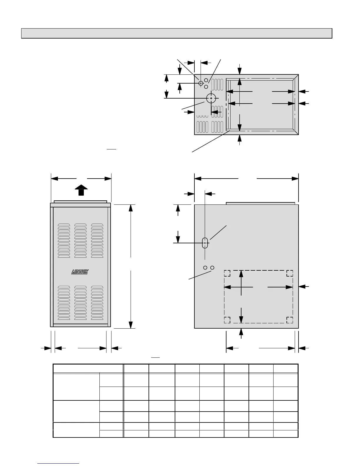
G24M Unit Dimensions - inches (mm)
SUPPLY
AIR
OPENING
*C
FLUE
OUTLET
D
*191/2
(495)
2 (51)
E
1
(25)
1
(25)
1
(25)
GAS PIPING
INLET
ELECTRICAL INLETS
(Top & Bottom)
41/4
(105)
*19
(483)
1
(25)
*NOTE - The supply air opening is equipped with a 3/4 inch (19 mm)
scored flange that may be bent 90 for plenum connection. The dimen
sions shown were taken after the flange was bent.
A
B
**C
RETURN AIR
KNOCKOUT
(Either Side)
Return Air
Opening
Return Air
Opening
GAS PIPING
INLET
(Both Sides)
ELECTRICAL
INLETS
(Either Side)
AIR FLOW
FRONT VIEW SIDE VIEW
TOP VIEW
F Left Side
G Right Side
2 (51)
295/8
(752)
**191/2
(495)
191/2
(495)
15
(381)
1
(25)
1
(25)
1
(25)
1
(25)
3/4 (19)
**NOTE The return air opening is
equipped with a 3/4 inch (19 mm) scored
flange that may be bent 90 for plenum
connection. The dimensions shown were
taken after the flange was bent.
The double scored flange at the front of the supply air open
ing may be bent for a total opening dimension (front to rear)
of either 191/2 inches (495 mm) or 19 inches (483 mm).
Model No. A B C D E F G
G24M245
G24M260
in. 17 361/4 15 63/4 27/16 111/2 61/2
G24M360
G24M375
G24M475
mm 432 921 381 171 62 293 165
G24M3/4100
G24M3/4120
in. 201/2 39 181/2 83/8 41/4 13 8
G24M4/5100
G24M4/5120
mm 521 991 470 213 108 331 203
in. 231/4 39 211/4 9-3/4 41/4 12-31/32 73/32
G24M4/5140
mm 591 991 540 248 108 329 180
 Loading...

