Page 19
6 - After determining that each appliance remaining con
nected to the common venting system properly vents
when tested as indicated in step 3, return doors, win
dows, exhaust fans, fireplace dampers and any other
gasburning appliance to their previous condition of
use.
7 - If improper venting is observed during any of the
above tests, the common venting system must be cor
rected. The common venting system should be re
sized to approach the minimum size as determined by
using the appropriate tables in appendix G in the cur
rent standards of the National Fuel Gas Code ANSI
Z223.1 in the USA, and the appropriate Category 1
Natural Gas and Propane appliances venting sizing
tables in the current standards of the CAN/CGA
B149.1 and B149.2 in the Natural Gas and Propane
Installation Code in Canada.
Horizontal Venting
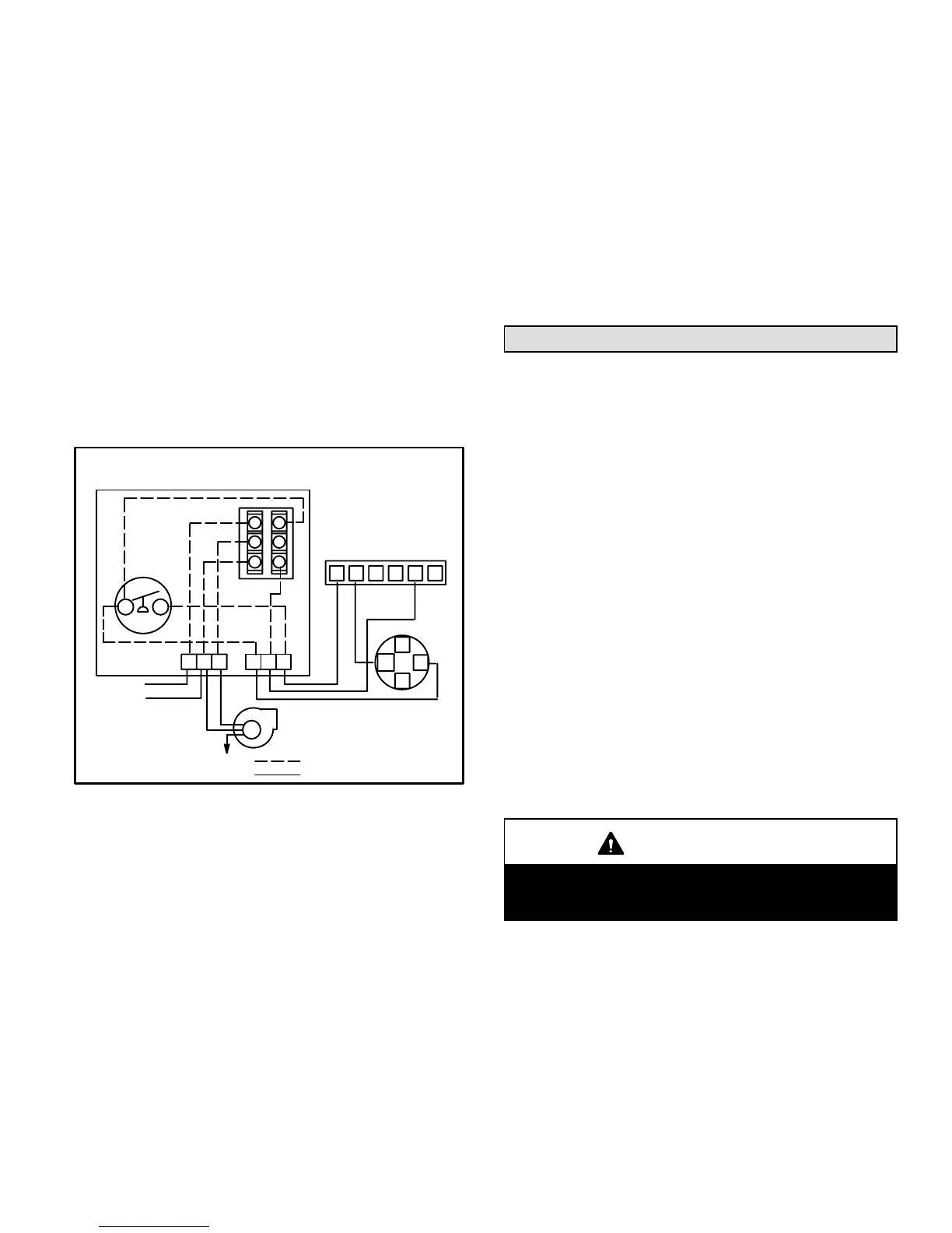
Side Wall Venting Kit Wiring
C
L1
L2
120VAC
M
L1 MN
T1 T2 T3
WR Y G
W
G
R
Y
24 VAC
THERMOSTAT
THERMOSTAT CONNECTIONS
TERMINAL IN FURNACE
JUNCTION BOX
RELAY
CK-43 CONTROL BOX
PRESSURE
SWITCH
SWG
POWER
VENTER
MOTOR
T
FIELD-INSTALLED WIRING
FACTORY-INSTALLED WIRING
NO
2
1
3
5
4
FIGURE 17
This furnace design is certified by the American Gas
Association and the Canadian Gas Association for hori
zontal venting through an outside wall only with the use of a
Field Controls Company Model SWG4L side wall venting
kit available as Lennox part number 79J15. No other Field
brand venting kit or any other manufacturer's venting kit is
acceptable. Horizontal venting of this furnace without the
use of the above stated kit is prohibited. See figure 17 for
field wiring of side wall horizontal venting kit.
When horizontally vented, the minimum clearance for
termination from electric meters, gas meters, regulators
and relief equipment is 4 feet (1.2 m) for US installations.
Refer to the current CAN/CGA B149.1 and B149.2 for
installations in Canada or with authorities having local ju
risdiction.
At vent termination, care must be taken to maintain pro
tective coatings over building materials (prolonged expo
sure to exhaust condensate can destroy protective coat
ings). It is recommended that the exhaust outlet not be
located within 6 feet (1.8 m) of a condensing unit because
the condensate can damage the painted coating.
Gas Piping
GAS SUPPLY
1 - This unit is shipped standard for left or right side instal
lation of gas piping (or top entry in horizontal applica
tions). Connect the gas supply to the piping assembly.
2 - When connecting the gas supply, factors such as
length of run, number of fittings and furnace rating
must be considered to avoid excessive pressure drop.
Table 10 lists recommended pipe sizes for typical ap
plications.
3 - The gas piping must not run in or through air ducts,
clothes chutes, gas vents or chimneys, dumb waiters
or elevator shafts.
4 - The piping should be sloped 1/4 inch (6.4 mm) per 15 feet
(4.57 m) upward toward the meter from the furnace. The
piping must be supported at proper intervals [every 8 to
10 feet (2.44 to 3.01 m) using suitable hangers or straps.
A drip leg should be installed in vertical pipe runs to the
unit.
5 - In some localities, codes may require installation of a
manual main shutoff valve and union (furnished by
the installer) external to the unit. Union must be of the
ground joint type.
IMPORTANT
Compounds used on threaded joints of gas piping
must be resistant to the actions of liquified petro
leum gases.
NOTE - Install a 1/8 inch NPT plugged tap in the field piping
upstream of the gas supply connection to the unit. The tap
must be accessible for test gauge connection. See figure 18.
NOTE - In case emergency shutoff is required, shut off main
manual gas valve and disconnect main power to unit. These
devices should be properly labeled by the installer.
 Loading...

