Page 25
Heating Sequence Of Operation
1 - When thermostat calls for heat, combustion air blower
starts.
2 - Combustion air pressure switch proves blower opera
tion. Switch is factory set and requires no adjustment.
3 - After a 15 second prepurge, hot surface ignitor ener
gizes.
4 - After a 20 second ignitor warm-up period, gas valve
solenoid opens.
5 - Gas is ignited, ignition sensor proves the flame and
combustion process continues.
6 - If flame is not detected after first ignition trial, ignition
control will repeat steps 3 and 4 four more times before
locking out the gas valve (WATCHGUARD" flame fail
ure mode). Ignition control will then automatically re
peat steps 3, 4, 5 and 6 after 60 minutes.
7 - To interrupt the 60-minute WATCHGUARD" period,
move thermostat from Heat" to OFF" then back to
Heat." Heating sequence then restarts at step 1.
Gas Pressure Adjustment
Gas Flow
To check for proper gas flow to the combustion chamber, de
termine the Btu (kW) input from the unit rating plate. Divide this
input rating by the Btu (kW) per cubic foot (cubic meter) of
available gas. The result is the required number of cubic feet
(cubic meter) per hour. Determine the flow of gas through the
gas meter for two minutes and multiply by 30 to get the hourly
flow of gas.
Gas Pressure
1 - Check the gas line pressure with the unit firing at maxi
mum rate. A minimum of 4.5 in. w.c. for natural gas or
11.0 in. w.c. for LP/propane gas should be maintained.
2 - After the line pressure has been checked and ad
justed, check the regulator pressure. Manifold pres
sures are given in table 11. See figures 23 and 24 for
manifold pressure adjustment screw location.
Note - A natural gas to LP/propane gas changeover kit is
required to convert the unit.
High Altitude Information
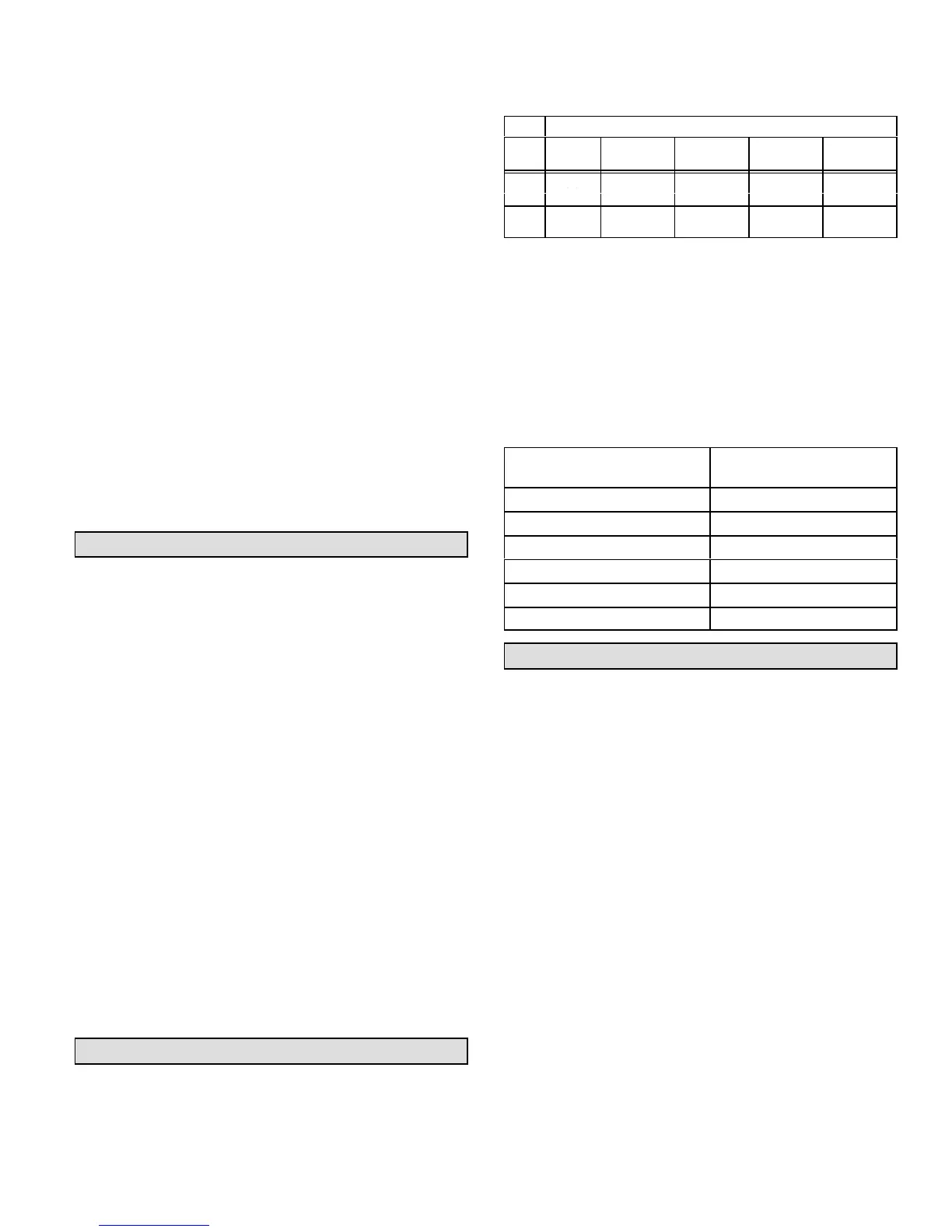
Refer to table 11 for manifold pressure settings for installa
tions at different altitudes and for different fuels.
TABLE 11
MANIFOLD ABSOLUTE PRESSURE (OUTLET) IN. W.C. (KPA)
Altitude - feet (m) above sea level
FUEL
0-2000
(0-610)
2000-4500
(610-1372)
4500-5500
(1372-1676)
5500-6500
(1676-1981)
6500-7500
(1981-2286)
3.5
*
(0.87)
.
.
.
.
.
.
.
.
9.5
*
LP
.
(2.36)
9.5 (2.36
9.2 (2.29) 8.9 (2.21) 8.6 (2.14)
*No adjustment required.
NOTE - In Canada, certification for installations at eleva
tions over 4500 feet (1372 m) is the jurisdiction of local au
thorities.
The combustion air pressure switches are factory-set and
require no adjustment.
At elevations of 4500 feet (1372 m) or greater, replace the
factoryinstalled pressure switch with the switch listed in
table 12.
TABLE 12
Unit Model
Pressure Switch
Part Number
G24M-45 NO CHANGE
G24M-60 NO CHANGE
G24M-75 88J8001
G24M-100 18L2401
G24M-120 18L2401
G24M-140-7 NO CHANGE
Other Unit Adjustments
Primary and Secondary Limits
The primary limit is located on the heating compartment ves
tibule panel. Two secondary limits are located in the blower
compartment, behind the blower. These limits are factory-set
and require no adjustment.
Flame Rollout Switches (Two)
These manually reset switches are located just above the
burner box. If tripped, a check for adequate combustion air
should be made before resetting.
Combustion Air Pressure Switch
The combustion air pressure switch is located on the heat
ing compartment vestibule panel. This switch checks for
proper combustion air blower operation before allowing
ignition trial. The switch is factory-set and requires no ad
justment.
Fan Control
The fan on time of 45 seconds is not adjustable. Fan off
time (time that the blower operates after the heat demand
has been satisfied) can be adjusted by flipping the dip
switches located on the Surelight integrated control. The
unit is shipped with a factory fan off setting of 90 seconds.
Fan off time will affect comfort and is adjustable to satisfy
individual applications. See figure 25.
 Loading...

