Page 27
Service
WARNING
Disconnect power before servicing unit.
CAUTION
Label all wires prior to disconnection when servicing
controls. Wiring errors can cause improper and danger
ous operation. Verify proper operation after servicing.
At the beginning of each heating season, service items A
through E as described below:
A - Electrical
1 - Check all wiring for loose connections.
2 - Check for the correct voltage at the furnace (furnace
operating).
3 - Check amp-draw on the blower motor.
Motor Nameplate__________Actual__________
B - Blowers
Check the blower wheels for debris and clean if necessary.
The blower motors are prelubricated for extended bearing
life. No further lubrication is needed.
C - Filters
All G24M filters are installed external to the unit. Filters
should be inspected monthly. Clean or replace the filters
when necessary to ensure proper furnace operation. See
table 13 for filter sizes. Replacement filters for
G24M-45/60/75 units must have a minimum velocity rating
of 400 FPM. Replacement filters for G24M-100/120/140
units require a minimum velocity rating of 625 FPM.
TABLE 13
Model Number Filter Size - inches (mm)
G24M-45/60/75 16 X 20 X 1 (406 X 508 X 25)
G24M-100/120/140 20 X 20 X 1 (508 X 508 X 25)
WARNING
The blower access panel must be securely in place
when the blower and burners are operating. Gas fumes,
which could contain carbon monoxide, can be drawn
into living space resulting in personal injury or death.
D - Flue And Chimney
Check the flue pipe, chimney and all connections for tight
ness and to make sure there is no blockage.
E - Burners
Inspect the burners and burner flame at the beginning of
each heating season. If necessary, clean the burners as in
dicated below:
1 - Turn off the electrical and gas supply to the furnace.
2 - Remove the burner box top.
3 - Remove the burner retaining bracket.
4 - Remove the burners.
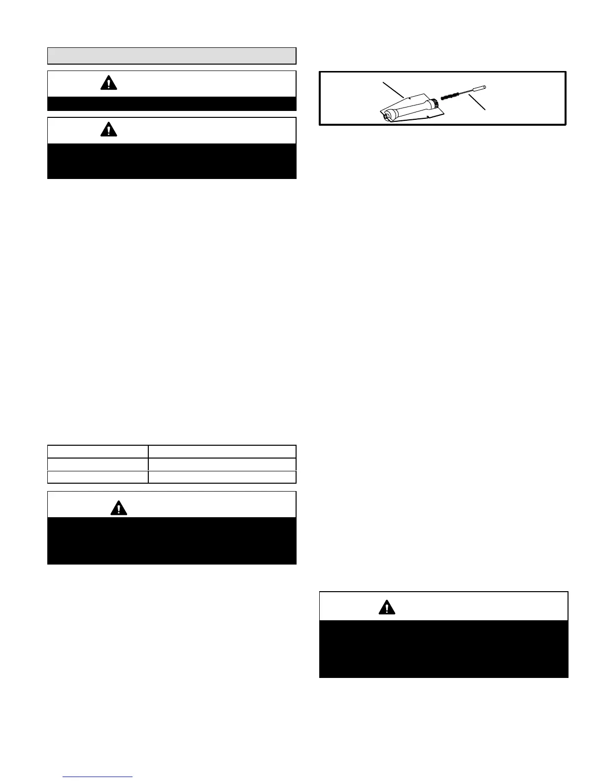
5 - Clean the inside of each burner with a bottle brush as
shown in figure 27.
Cleaning Burners
BOTTLE
BRUSH
BURNER
FIGURE 27
6 - Replace the burners and the burner retaining bracket.
Make sure the burners are properly seated in the slots
on the tray. The burner orifice must be aligned with the
manifold.
7 - Reinstall the burner box top.
8 - Restore electrical power and gas supply to the furnace.
Follow lighting instructions on the front of the unit.
Check the appearance of the burner flame, burner
pressure, gas flow, and temperature rise. If necessary,
make adjustments. See the other unit adjustments sec
tion.
Heat Exchanger
Periodically inspect the heat exchanger tubes and the flue
box for corrosion and soot deposits. If necessary, clean as
indicated below:
1 - Turn off the electrical and gas supply to the furnace.
2 - Disconnect the wiring to the combustion air fan.
3 - Remove the screws securing the flue box to the furnace.
Clean the flue box with a wire brush (brassbristle brush
recommended), and rags or a shop vacuum cleaner.
4 - Disconnect the gas supply piping and the ignitor and
sensor wires. Remove the burner assembly from the
furnace.
5 - Since the heat exchanger tubes are crimped in several
locations, a thorough cleaning of the entire length of
each tube is not possible. However, remove any soot
deposits which are accessible with a wire brush (brass
bristle brush recommended), and rags or a shop vacuum
cleaner.
6 - Reinstall the flue box using a new gasket.
7 - Reconnect the combustion air fan wiring.
8 - Reinstall the burner box, ignitor and sensor wires and
the gas supply piping.
9 - Carefully check all piping connections (factory and field)
for gas leaks. Use a leak detecting solution or other pre
ferred means.
IMPORTANT
Some soaps used for leak detection are corrosive to
certain metals. Carefully rinse piping thoroughly af
ter leak test has been completed. Do not use
matches, candles, flame or other sources of ignition
to check for gas leaks.
10 Restore electrical power and gas supply. Follow light
ing instructions on front of unit. Check burner flame
and adjust if necessary.
 Loading...

