Page 14
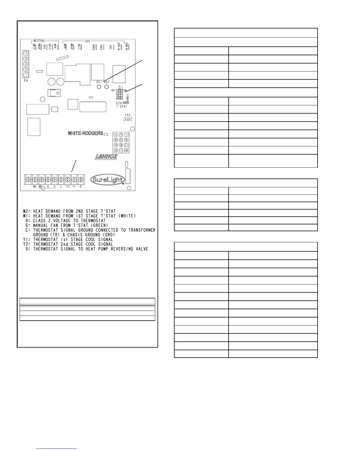
CONTROL BOARD 18M34
FIGURE 4
THERMOSTAT CONNECTIONS (TB1)
DIP
SWITCHES
1 − 4
LEDs
FACTORY−
INSTALLED
JUMPER
DIP SWITCH(ES) FUNCTION
1 and 2 Blower Off Delay (Heating Mode)
3 Second Stage ON Delay (Single−stage t’stat)
4 Blower Off Delay (Cooling Mode)
TABLE 3
Integrated Control Board Terminals
120VAC Neutral
LINE Line
XFMR Transformer
EAC Electronic Air Cleaner
CIRC Indoor Blower
HUM Humidifier
120VAC Line
HUM Humidifier
XMFR Transformer
LINE Line
PARK For Unused Leads
COOL Cooling Speed
EAC Electronic Air Cleaner
HI HEAT HIigh Heat Speed
LO HEAT Low Heat, Low Cool and Continuous Fan
Speed
TABLE 4
Integrated Control Board 5 Pin Terminal
PIN # Function
1 Ignitor
2 Combustion Air Inducer High Speed
3 Combustion Air Inducer Low Speed
4 Combustion Air Inducer Neutral
5 Ignitor Neutral
TABLE 5
Integrated Control Board 12Pin Terminal
PIN # Function
1 Gas Valve 2nd Stage (High Fire)
2 Second Stage Prove Switch
3 Not Used
4 Ground
5 24V Hot
6 Primary Limit In
7 Gas Valve 1st stage (Low Fire)
8 Gas Valve Common
9 24V Neutral
10 Ground
11 Primary Limit Out
12 1st Stage Prove Switch
 Loading...


