Page 15
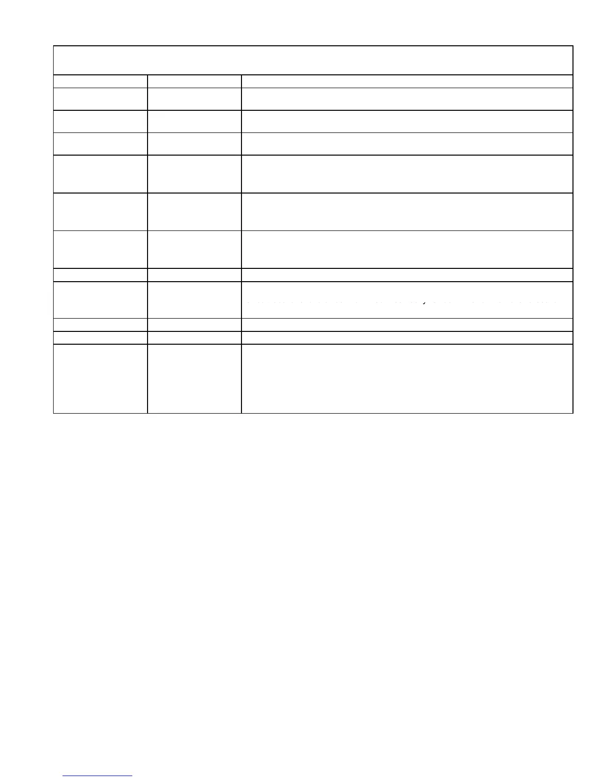
TABLE 6
DIAGNOSTIC CODES
Diagnostic LEDs are labeled DS1 and DS2. See figure 4 for location of diagnostic LEDs.
DS1 DS2 DESCRIPTION
SIMULTANEOUS
SLOW FLASH
SIMULTANEOUS
SLOW FLASH
Power on − Normal operation.
Also signaled during cooling and continuous fan.
SIMULTANEOUS
FAST FLASH
SIMULTANEOUS
FAST FLASH
Normal operation − signaled when heating demand initiated at thermostat.
SLOW FLASH ON
Primary, secondary or rollout limit switch open. Limits must close within 3 minutes
or unit goes into 1 hour Watchguard.
OFF SLOW FLASH
Low pressure switch open;
OR: Blocked inlet/exhaust vent;
OR: Low pressure switch closed prior to activation of combustion air inducer.
OFF FAST FLASH
High pressure switch open;
OR: Blocked inlet/exhaust vent;
OR: High pressure switch closed prior to activation of combustion air inducer.
ALTERNATING
SLOW FLASH
ALTERNATING
SLOW FLASH
Watchguard −− burners failed to ignite; OR limit open more than 3 minutes;
OR lost flame sense 5 times in one heating cycle;
OR pressure switch opened 5 times in one heating cycle.
SLOW FLASH OFF Flame sensed without gas valve energized.
ON ON
FAST FLASH SLOW FLASH Main power polarity reversed. Switch line and neutral.
SLOW FLASH FAST FLASH Low flame signal. Measures below 0.23 microAmps. Replace flame sense rod.
ALTERNATING
FAST FLASH
ALTERNATING
FAST FLASH
The following conditions are sensed during the ignitor warm−up period only:
1) Improper main ground;
2) Broken ignitor; OR: Open ignitor circuit;
3) Line voltage below 75 volts.
(If voltage lower than 75 volts prior to ignitor warm-up, control will signal waiting on
call from thermostat, and will not respond.
NOTE − Slow flash rate equals 1 Hz (one flash per second). Fast flash rate equals 3 Hz (three flashes per second).
Low flame sense current = 0.17−0.22 microAmps.
 Loading...


