Page 23
11. Primary Limit Control (S10)
The primary limit (S10) on G60UH(X) units is located in the
heating vestibule panel. When excess heat is sensed in the
heat exchanger, the limit will open. If the limit is open, the fur-
nace control energizes the supply air blower and closes the
gas valve.The limit automatically resets when unit temperature
returns to normal. The switch must reset within three minutes
or the SureLight board will go into Watch guard for one hour. If
the limit opens during a second stage heat call, the blower
will operate on high heat for 30 seconds and then switch to
low heat speed for the remainder of the 3 minute period. The
switch is factory set (see face of switch) and cannot be ad-
justed. Replace switch with exact length and set point.
12. Secondary Limit Controls (S21)
The secondary limit (S21) on G60UH(X) units is located in the
blower compartment on the back side of the blower housing.
See figure 6. Blower speed chart on the wiring diagram show
secondary limit quantities per unit. When excess heat is
sensed in the blower compartment, the limit will open. If the
limit is open, the furnace control energizes the supply air blow-
er and closes the gas valve. The limit automatically resets
when unit temperature returns to normal. G60UH−1 through −4
units use surface type limts factory set to open at 125°F.
G60UH−5 units and later use air stream type limts factory set
to open at 135°. The secondary limit cannot be adjusted.
13. Gas Valve
The G60UH(X) uses a two−stage gas valve manufactured
by Honeywell (figure 14). The valve is internally redundant
to assure safety shut−off. If the gas valve must be replaced,
the same type valve must be used.
24VAC terminals and gas control knob or switch are located
on the valve. All terminals on the gas valve are connected to
wires from the electronic ignition control. 24V applied to the ter-
minals energizes the valve.
Inlet and outlet pressure taps are located on the valve. A regu-
lator adjustment screw is located on the valve.
LPG change over kit s are available from Lennox. Kits include
burner orifices and a gas valve regulator conversion kit.
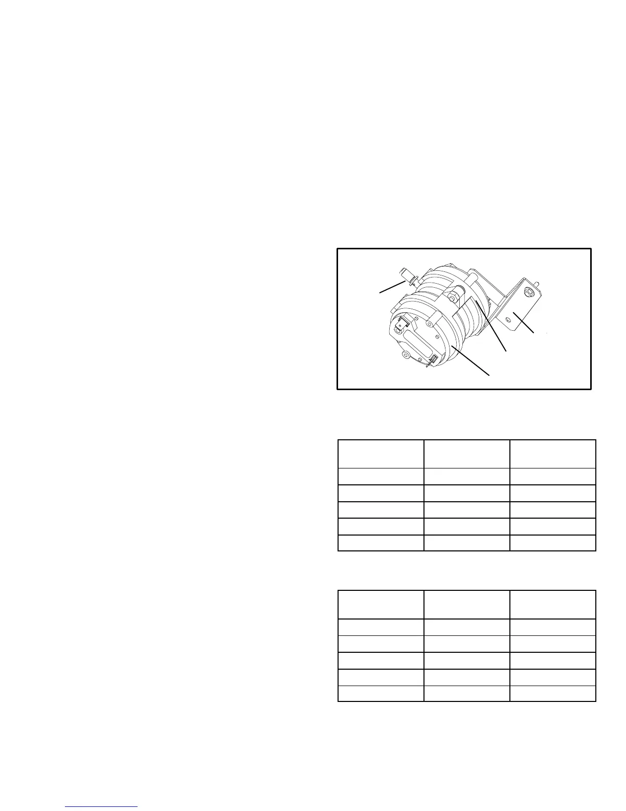
14. Combustion Air Inducer
Prove Switch (S18)
G60UH(X) series units are equipped with a dual combustion
air proving switch (first and second stage) located on the
combustion air inducer orifice bracket. The switch is con-
nected to the combustion air inducer housing by means of a
flexible silicone hose. It monitors negative air pressure in the
combustion air inducer housing.
The switches are a single-pole single-throw proving switch
electrically connected to the furnace control. The purpose of
the switch is to prevent burner operation if the combustion
air inducer is not operating or if the flue becomes obstructed.
On heat demand (first or second stage) the switch senses
that the combustion air inducer is operating. It closes a cir-
cuit to the furnace control when pressure inside the com-
bustion air inducer decreases to a certain set point.
Set points vary depending on unit size. See tables 12, 13
and 14. The pressure sensed by the switch is negative rela-
tive to atmospheric pressure. If the flue becomes ob-
structed during operation, the switch senses a loss of neg-
ative pressure (pressure becomes more equal with atmo-
spheric pressure) and opens the circuit to the furnace con-
trol and gas valve. A bleed port on the switch allows rela-
tively dry air in the vestibule to purge switch tubing, to pre-
vent condensate build up.
The switch is factory set and is not field adjustable. It is a
safety shut-down control in the furnace and must not be by−
passed for any reason. If switch is closed or by−passed, the
control will not initiate ignition at start up.
FIGURE 13
DUAL COMBUSTION AIR PROVE SWITCH
BRACKET
TAP
LOW FIRE SWITCH
HIGH FIRE SWITCH
TABLE 12
0’ to 4500’
G60UH(X) Unit
Set Point High
Heat
Set Point Low
Heat
−045 0.40" 0.20"
−070 0.40" 0.20"
−090 0.45" 0.20"
−110 0.50" 0.20"
−135 0.50" 0.20"
TABLE 13*
4501’ to 7500’
G60UH(X) Unit
Set Point High
Heat
Set Point Low
Heat
−045 0.40" 0.20"
−070 0.40" 0.20"
−090 0.40" 0.20"
−110 0.45" 0.20"
−135 0.45" 0.20"
*Unit requires conversion kit at this altitude. See High Altitude table.
 Loading...


