Page 22
9. Combustion Air Inducer (B6)
All G60UH(X) units use a two−stage combustion air inducer
to move air through the burners and heat exchanger during
heating operation. The blower uses a 120VAC motor. The
motor operates during all heating operation and is con-
trolled by furnace / blower control A92. The inducer also
operates for 15 seconds before burner ignition (pre-purge)
and for 5 seconds after the gas valve closes (post-purge).
The inducer operates on low speed during first−stage heat,
then switches to high speed for second stage heat.
A proving switch connected to the combustion air inducer ori-
fice plate is used to prove inducer operation. The combustion
air inducer orifice will be different for each model. See table 11
for orifice sizes. The switch monitors air pressure in the induc-
er housing. During normal operation, the pressure in the
housing is negative. If pressure becomes less negative (sig-
nifying an obstruction) the proving switch opens. When the
proving switch opens, the furnace control (A92) immediately
closes the gas valve to prevent burner operation.
TABLE 11
G60UH(X) Unit
C.A.I. Orifice Size
−045−1, −2 1.25"
−070−1, −2, −3 1.5"
−070−4 and later 1.438"
−090 all units 1.75"
−110−1, −2, −3 2.0"
−110−4 and later 1.875"
−135−1, −2, −3 2.25"
−135−4 and later 2.156"
Horizontal Applications
The G60UH(X) furnace can be installed in horizontal ap-
plications.
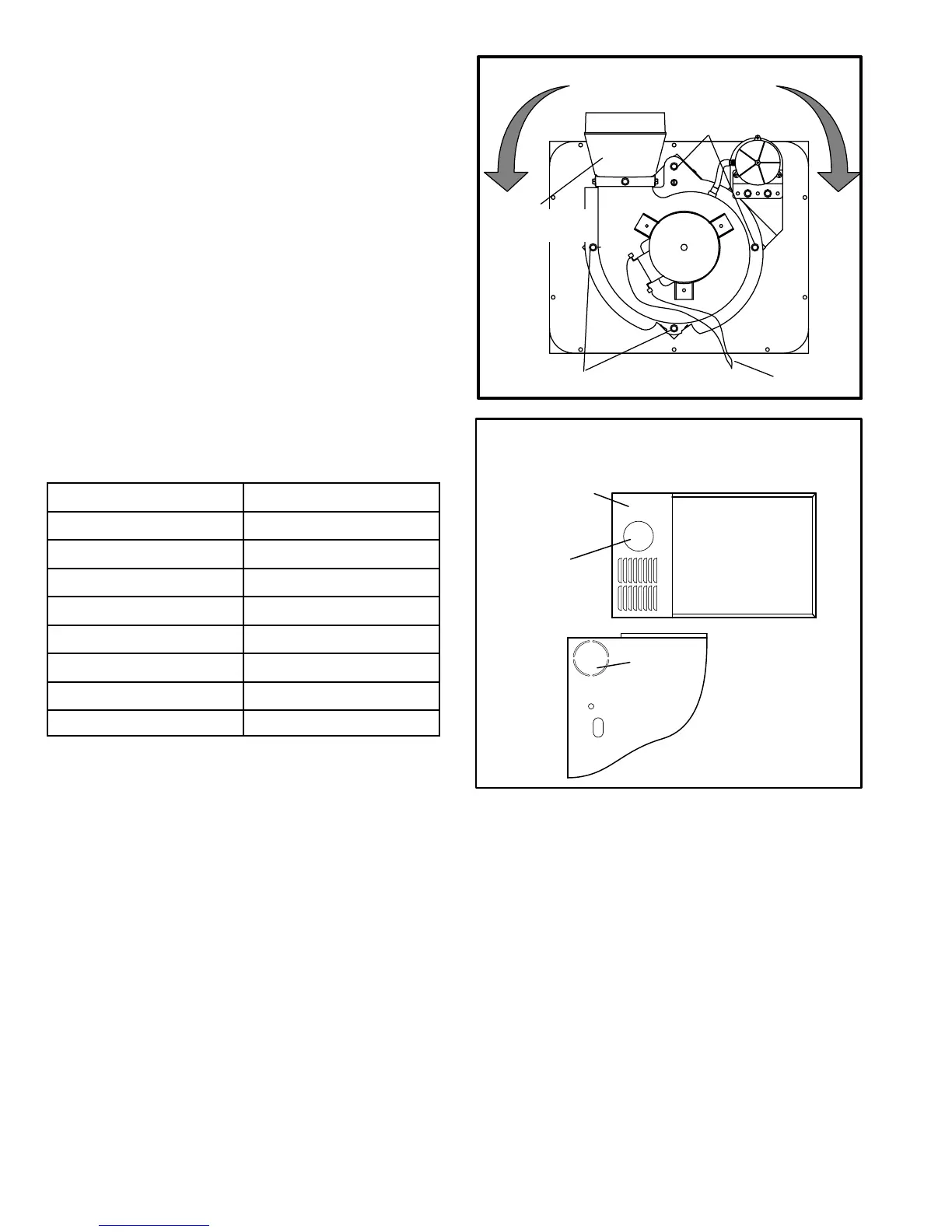
The combustion air inducer may be rotated clockwise or
counterclockwise by 90° to allow for vertical vent discharge
in a horizontal application. Remove the four mounting
screws, rotate the assembly (assembly consists of orifice
plate, proving switch, gasket and combustion air inducer),
then reinstall the mounting screws. See figure 11. Use the
provided wire tie to bundle the pressure switch wires with
the inducer motor power leads. Route the wires away
from moving parts and the heat of the inducer motor to
prevent damage to the wires. Use sheet metal shears to
remove the cut out from the side of the cabinet. See figure
12. Use the two provided sheet metal screws to install the
cut out on the top cap to cover the original flue outlet open-
ing.
Combustion Air Inducer
(Upflow Position)
Mounting Screws
MOUNTING SCREWS
90°
90°
(Remove)
(Remove)
Power Leads
Flue Transition
(Do not remove
)
FIGURE 11
Flue Outlet Hole
(
Reattach
Cutout Here)
Supply Air
Opening
Top View of Furnace
Top Cap
Cut out
Optional
Flue Outlet
Optional Flue Outlet
(Horizontal Installation)
FIGURE 12
10. Flame Rollout Switches (S47)
On all G60UH −1, −2 and −3 units, flame rollout switch is a
high temperature limit located on top of the burner box.
Each furnace is equipped with two identical switches. One
switch is located over the leftmost burner and the other
switch is located over the rightmost burner. On G60UH−4
and later model units, the switches are located on a bracket
inside the burner box. The limits are N.C. SPST manual-re-
set limits. When S47 senses rollout, the circuit breaks and
the ignition control immediately stops ignition and closes
the gas valve.
If unit is running and flame rollout is detected, the gas valve
will close and ignition control will be disabled. Rollout can
be caused by a blocked heat exchanger, flue or lack of
combustion air. The switch is factory set to trip (open) at
210°F and cannot be adjusted. The switch can be manually
reset. To manually reset a tripped switch, push the reset but-
ton located on the control.
 Loading...


