G61MPVT − 50hz / Page 7
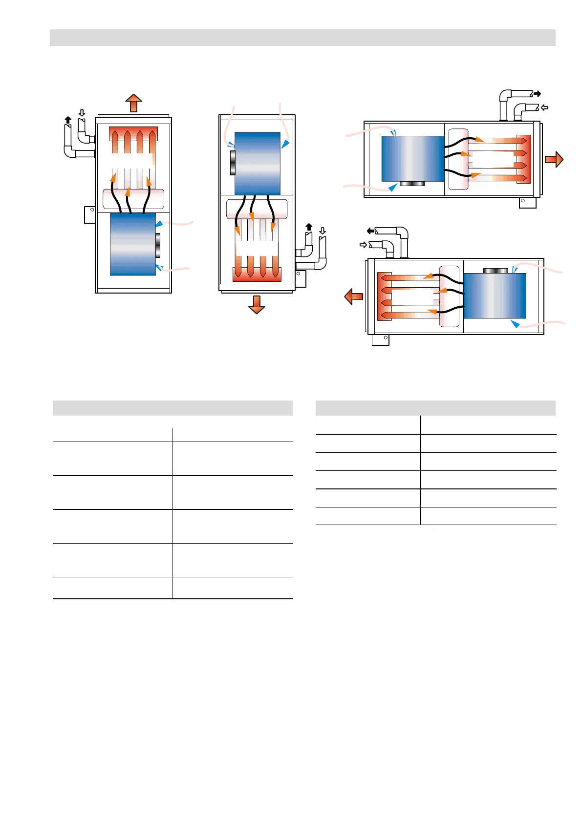
INSTALLATION CONFIGURATIONS
HEAT
EXCHANGER
HEAT
EXCHANGER
HEAT
EXCHANGER
HEAT
EXCHANGER
BLOWER
BLOWER
BLOWER
BLOWER
CONDENSATE
DRAIN
CONDENSATE
DRAIN
CONDENSATE
DRAIN
CONDENSATE
DRAIN
VENT
PIPING
VENT
PIPING
VENT
PIPING
VENT
PIPING
AIR
FLOW
AIR
FLOW
AIR FLOW
AIR FLOW
HORIZONTAL − RIGHT
HORIZONTAL − LEFT
UP−FLOW
DOWN−FLOW
NOTE − On up−flow and down−flow configurations, the vent piping and
condensate drain can be moved to the other side of the unit. Vent piping
and drain must be installed on the same side of the unit with each other
unless optional Condensate Trap Alternate Location Kit (up−flow only) is
used. On horizontal installations the drain must be located at the bottom
and the vent piping at the top.
FILTER AIR RESISTANCE
For 25 mm Cleanable Filter (Field Provided)
L/s Pa
0 0
95 2
190 7
285 10
375 15
470 22
565 30
660 37
755 47
850 57
945 67
1040 82
1130 94
1225 109
INSTALLATION CLEARANCES
Sides
1
0 mm
Rear 0 mm
Top/Plenum 25 mm
Front 0 mm
Front (service/alcove) 610 mm
Floor
2
Combustible
1
Allow proper clearances to accommodate condensate trap and vent pipe
installation.
2
Clearance for installation on combustible floor if optional down−flow combustible
floor base is installed between furnace and combustible floor. Not required in
add-on cooling applications if installed in accordance with local codes Do not install
the furnace directly on carpeting, tile, or other combustible materials other than
wood flooring.

 Loading...


