Page 40
Are LEDs on panel lit?
Check wiring?
Does panel readily
switch between Zone,
Central and Off?
Does panel readily
switch between Cool,
Heat and Auto?
Does panel readily
switch between Fan
On and Auto?
Are wires run adjacent
to AC line voltage
wires?
Option 3 − Troubleshooting Harmony
®
II Zone Control with FM21
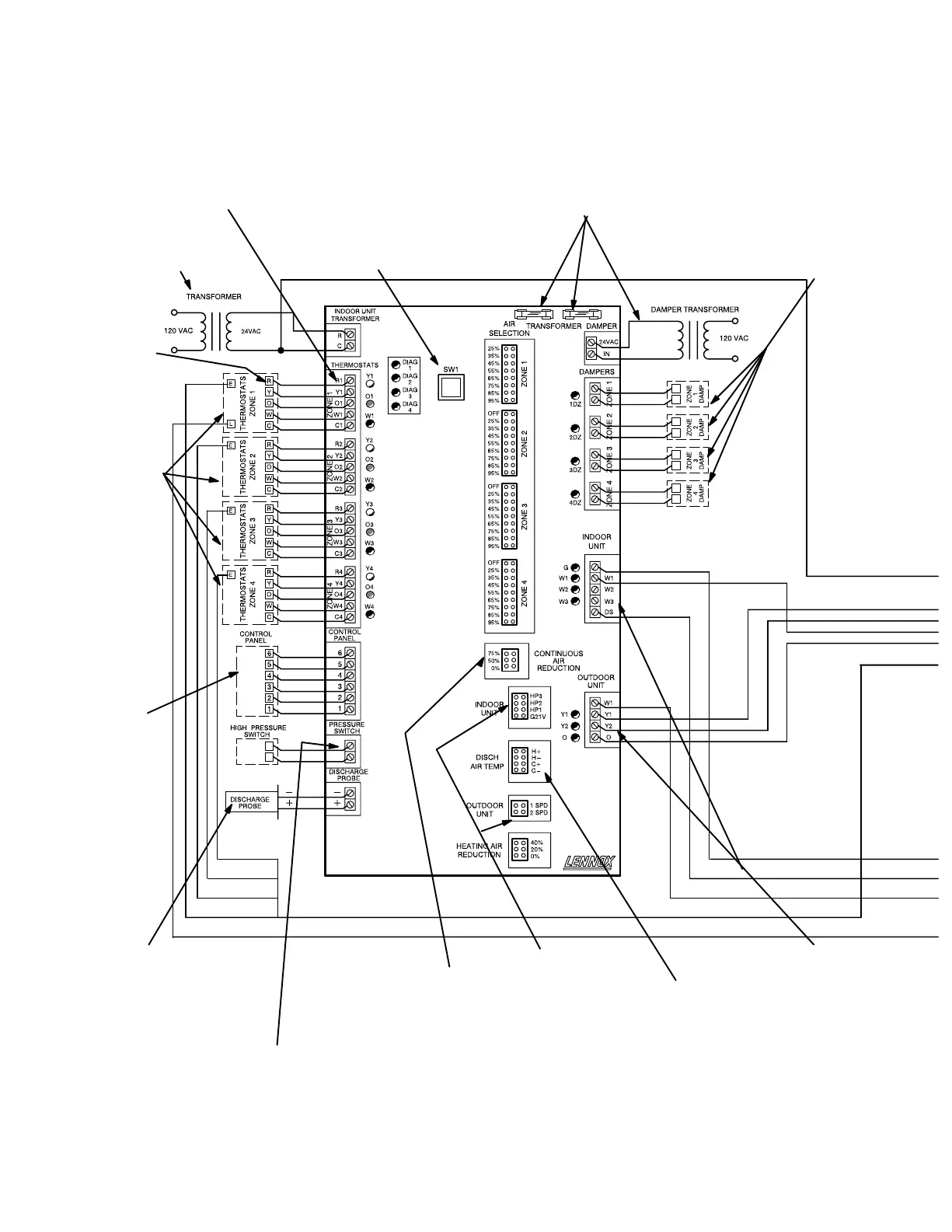
Figure 31
This troubleshooting diagram lists common trouble spots. Rather than providing solutions, this diagram asks questions about the hookup and
operation of system equipment. Good troubleshooting skills combined with information provided elsewhere in this manual are necessary.
or GAS
Is discharge probe installed?
Probe should be located in dis
charge air plenum before first
bend or branch. Is probe in cor
rect location?
Is it wired correctly?
After 5 minutes heating opera
tion, is discharge air between
95F and 125F?
After 5 minutes cooling opera
tion, is discharge air between
53F and 70F?
Heat pump thermo
stat used? (Must not
use heat/cool ther
mostat.)
If electronic thermo
stat is used, does it
have relay switching
output? If relay with
SCR output is used,
isolation relays may
need to be used.
24VAC supplied to
each thermostat ter
minal R from control
center?
Check each thermo
stat for output signal
when calling. Heating
output? Y1, Y2, W1.
Cooling output?
Y1, O, Y2 Blower out
put not used, no need
to check.
Are anticipators work
ing?
Error code present?
If so, see diagnostic
section of this manual.
Line voltage to trans
former?
24VAC from transform
er to control center?
Line voltage to transformer?
24VAC from transformer to control center?
Fuses OK?
Are all wire connections good? Are all wire
connections correct?
Are thermostats wired correctly?
Does control center respond ap
propriately to demand?
Are jumpers set
correctly?
Only one jumper
is allowed per zone.
Is wiring correct and in good condition?
Do dampers respond to demand? 0 volts AC =
open. 24 volts AC = closed. Dampers should drive
closed when 24 volts is jumpered to damper motor.
Up to two jumpers may be used.
If two jumpers are used, one must be on a
C terminal and the other on an H terminal.
Are appropriate outputs
energized in response to
demand?
Is switch installed in compressor discharge line between compressor and reversing valve?
Does switch open when high pressure condition is simulated (temporarily blocking airflow in
heating mode)?
Does control center respond appropriately when high pressure condition is simulated (tempo
rarily disconnecting switch simulates high pressure).
Is jumper set correctly? Heating air reduc
tion must be set to 0%.
Does jumper provide appropriate speed re
duction? If no, check indoor unit before re
placing control center.
Is jumper set correctly?
or GAS
 Loading...