Page 41
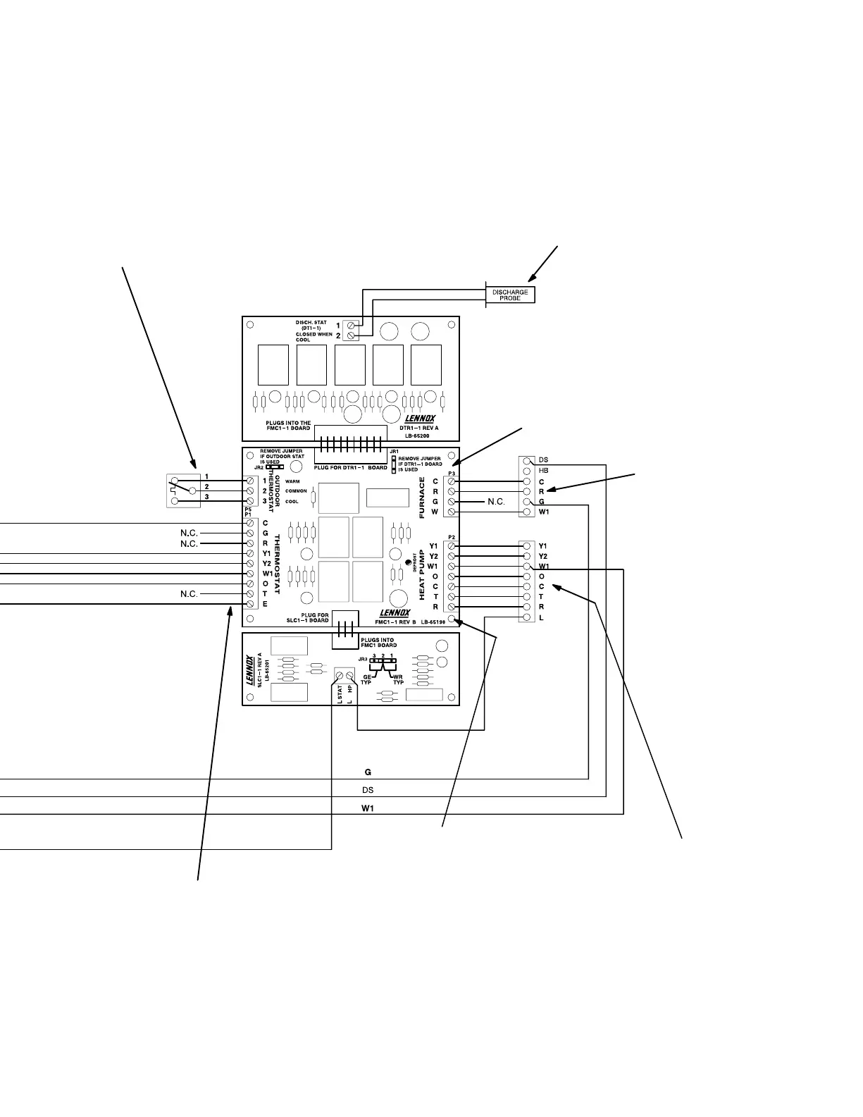
Figure 32
Indoor Unit
Outdoor Unit
Are appropriate inputs
being received?
Refer to FM21 input/
output tables in FM21
installation instruc-
tions.
Does outdoor unit respond to demand?
Is it operating properly?
Test defrost. Does outdoor unit initiate and terminate
defrost correctly?
Is W1 energized during defrost?
Does FM21 respond appropriately during defrost?
Does Harmony control center respond appropriately
during defrost?
24VAC from furnace trans-
former or 75VA transform-
er (DTR1 Option) to R"?
Does furnace respond to
ouputs? Cooling? Heat-
ing? Defrost? Em. Heat?
Does blower speed
change as zone demand
changes? If no, does DS
output vary from 0 to
25VDC?
Is discharge probe (DT1) installed?
Probe should be located between coil and fur-
nace. Is probe in correct location?
Is it wired correctly?
During defrost operation, does furnace cycle tem-
per discharge air?
Is outdoor (balance point) thermostat
installed?
Does systems use compressor heat
to satisfy primary heating demand
when above balance point?
Does system use gas heat to satisfy
primary heating demand when below
balance point?
Are jumpers correctly
installed?
Refer to FM21 instal-
lation manual.
Outdoor
Thermostat
DTR Kit (optional)
SLC Kit (optional)
FM21 Heat Pump Control
Option 3 − Troubleshooting Harmony
®
II Zone Control with FM21 (Cont’d)
This troubleshooting diagram lists common trouble spots. Rather than providing solutions, this diagram asks questions about the hookup and
operation of system equipment. Good troubleshooting skills combined with information provided elsewhere in this manual are necessary.
 Loading...