Page 19
FIGURE 14
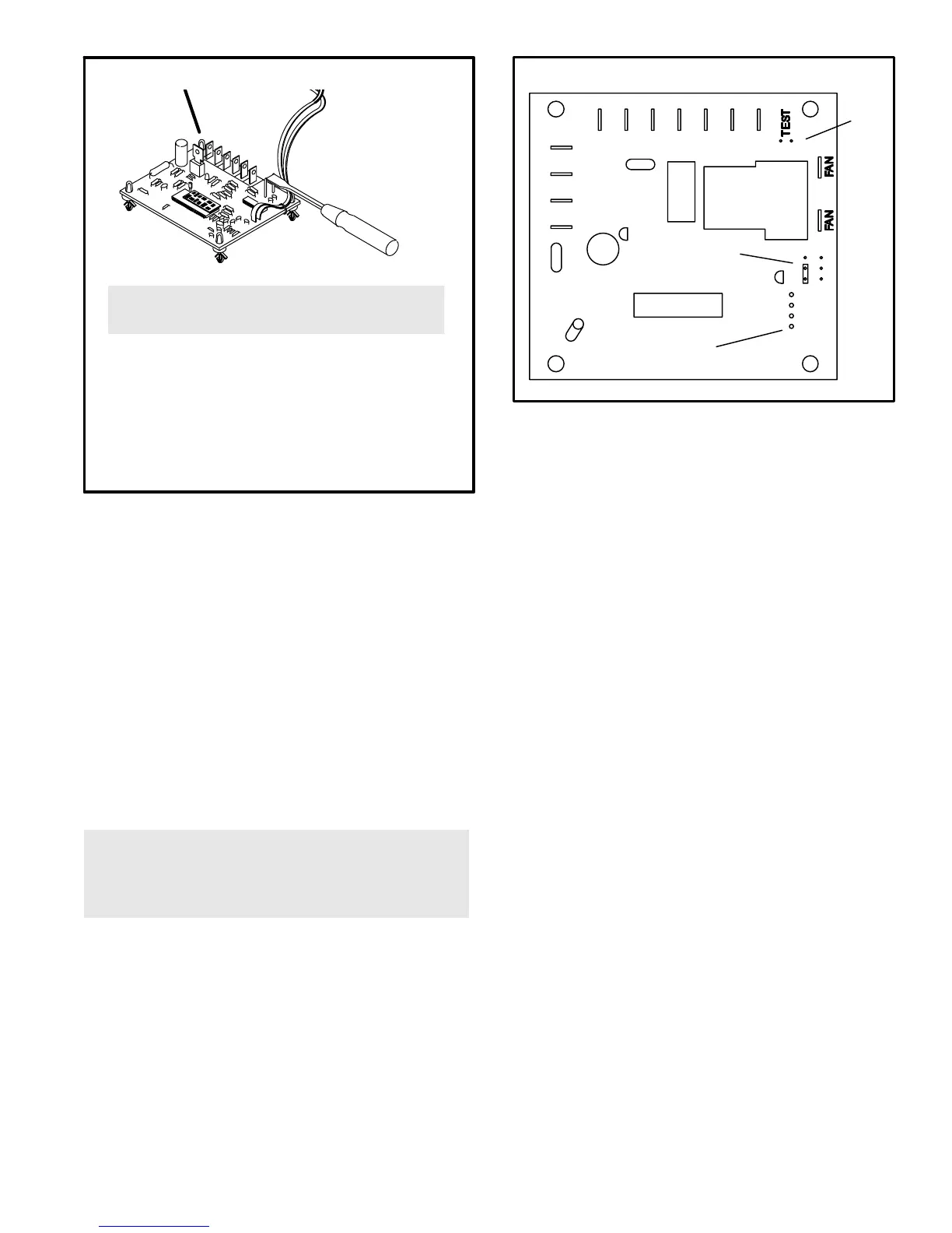
TO PLACE CONTROL IN TEST MODE:
1− Make sure all control terminals are connected as shown
on unit wiring diagram before attempting to place control
in test mode. See NOTE.
2− Turn indoor thermostat to heat mode and adjust to high-
est temperature setting.
NOTE − Control will not go into test mode when discon-
nected from unit. Unit load must be applied to control termi-
nals before the control will go into test mode.
3− With unit operating, momentarily short across TEST"
pins as shown.
4− LED should light and unit should operate in defrost mode
for at least 30 seconds or until normal termination.
5− To leave test mode, momentarily short across TEST"
terminals again.
WARNING − AVOID CONTACT WITH OTHER CONTROL
TERMINALS OR CONTROL COMPONENTS.
8− TEST" Pins
Each board is equipped with a set of test pins for use in
troubleshooting the unit. When momentarily shorted
together, these pins initiate a conventional defrost peri-
od. Because the defrost period was initiated by
momentarily shorting the two TEST" pins, the defrost
period must last a minimum of 30 seconds (see fig-
ure 14).
A defrost initiated by shorting the defrost pins together
can be terminated by shorting the defrost pins again.
Otherwise, defrost will be terminated as in normal op-
eration.
The defrost control continually self-tests its internal cir-
cuits. If an internal failure occurs, test mode will not
function and defrost LED will not light.
IMPORTANT − CONTROL WILL BEGIN TEST MODE
ONLY IF NORMAL LOAD IS APPLIED TO CONTROL
TERMINALS. DO NOT ATTEMPT TO OPERATE OR
TEST CONTROL OUT OF UNIT.
HP21−3 Units
HP21−3 units are equipped with a demand defrost system
which initiates a defrost cycle based on temperature differ-
ential and compressor run time. The control board includes
two permanently attached sensors which monitor coil and
outdoor ambient temperatures. The coil temperature sen-
sor is equipped with a spring clip which allows proper
positioning on the outdoor coil return bend. The ambient
temperature sensor is installed in a sampling tube at the
base of the unit. These sensors must not be detached from
the control board and must be replaced as part of the con-
trol board. Do not attempt to cut or splice the temperature
sensor wires.
Figure 15
CCWY ORR
Yout
CC
RV
C
AMB
COIL
SENSOR
CONNECTIONS
TEST
PINS
TERMINATION
TEMPERATURE
PINS
HP21−3 DEFROST CONTROL
Operation
When the reversing valve is de−energized, the Y1 circuit is
energized, and the coil temperature is below 35°F (2°C),
the board logs the compressor run time. When the unit is
initially started and the control is not calibrated, a defrost
cycle will be initiated after 34 minutes of heating mode com-
pressor run time. The control will terminate the defrost
cycle when the coil temperature rises above the preset ter-
mination temperature or after 14 minutes of defrost
operation. The termination temperature is factory set at
70°F. This setting may be adjusted in the field to 50°F
(10°C), 60°F (16°C), 70°F (21°C), or 80°F (27°C). The con-
trol will attempt to self−calibrate after this (and all other)
defrost cycle(s). Calibration success depends on stable
system temperatures during the 20−minute calibration peri-
od. If the board fails to calibrate, another defrost cycle will
be initiated after 34 minutes of heating mode compressor
run time. Once the defrost board is calibrated, it will use de-
mand defrost logic to initiate a defrost cycle. A demand
defrost system initiates defrost when the difference be-
tween the clear coil and frosted coil temperatures exceeds
the maximum difference allowed by the control.
If the control determines an ambient temperature sensor
failure and the coil temperature is 35°F (2°C) or lower, the
control will repeatedly initiate a defrost cycle after 34 min-
utes of heating mode compressor run time. If the control
determines that the coil temperature sensor has failed, the
control will not initiate a defrost cycle.
Test Mode
When Y1 is energized and 24V power is being applied to
the board, a test cycle (approximately 12 seconds) can be
initiated by placing the termination temperature jumper
across the Test" pins. If the jumper is applied to the test
pins before power is applied, or if the jumper is left across
the Test" pins longer than 5 minutes, the control will ignore
the test jumper and will revert to normal operation. The test
jumper will initiate continuous defrost cycles until the test
jumper is removed or the 5−minute test period ends.