Page 5
D−Hard Start Relay K31 (single-phase only)
All single-phase HP21 units are equipped with a hard start
relay located in the unit control box which controls the op-
eration of the compressor starting circuit. The relay is normally
closed when the compressor (contactor K1) is de-energized.
Capacitor (C7) is connected in series to a set of normally
closed K31 contacts and assists the compressor in starting.
When K1 energizes, the compressor immediately begins start-
up. K31 remains de-energized during compressor start-up and
the start capacitor (C7) remains in the circuit. As the compres-
sor gains speed K31 is energized by electromotive forces
generated by the compressor. When K31 energizes, its con-
tacts open to take the start capacitor out of the circuit.
E−Terminal Strip TB15
All HP21 units are equipped with a low voltage terminal
strip located in the unit control box for making up thermo-
stat wiring connections (refer to figure 2).
F−Compressor B1
See ELECTRICAL DATA or compressor nameplate for
specifications. Figure 3 shows the compressor terminal
box. All compressors are equipped with internal pressure
relief valves set at 450+50 psig. Compressors in all units
use insertion type crankcase heaters which are regulated
by relays in the HP21.
FIGURE 3
T3 T8 T1 T7
SINGLE
PHASE
T2
S1 S2
TYPICAL TWO-SPEED COMPRESSOR
TERMINAL BOX
COPELAND SINGLE-PHASE SHOWN
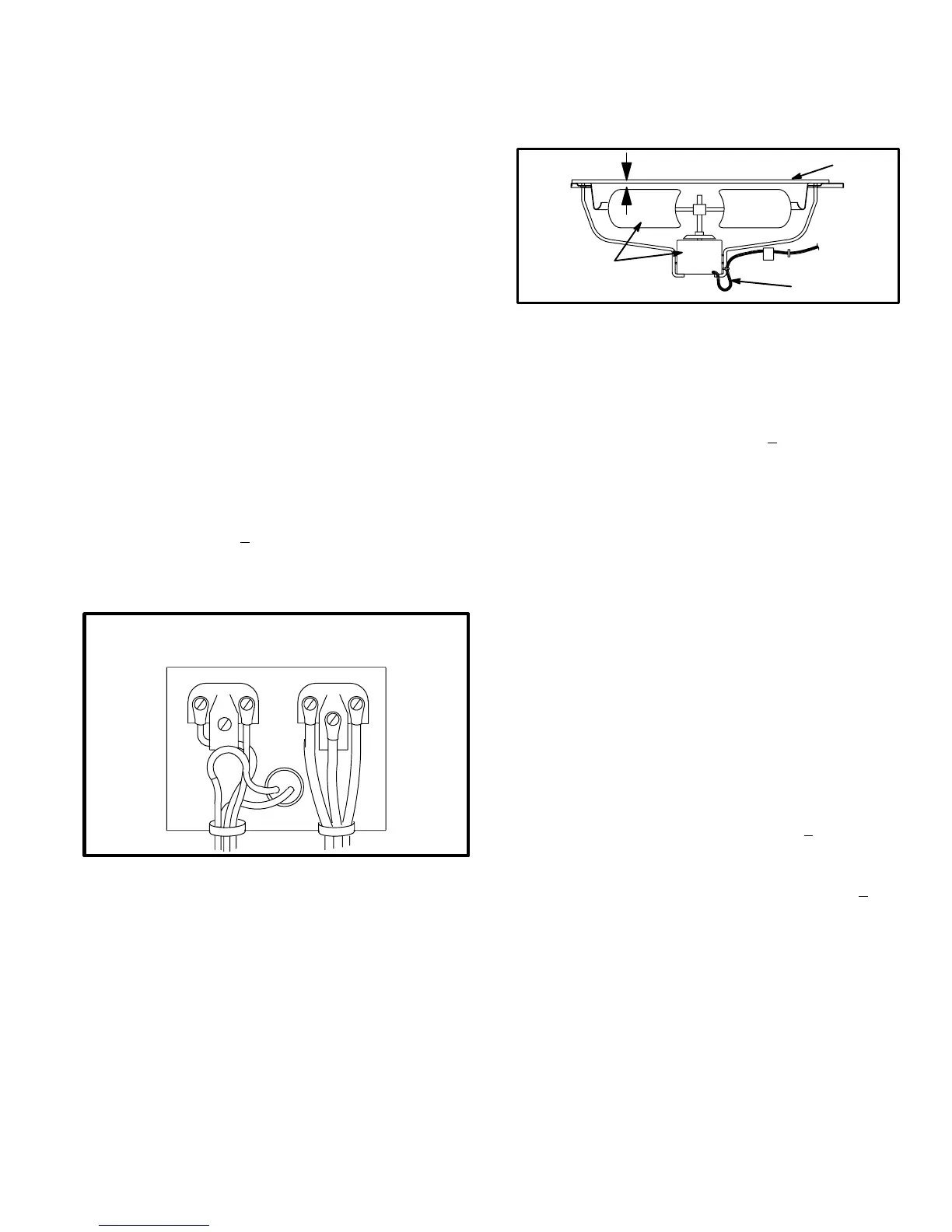
G−Outdoor Fan Motor B4
The specifications table on page 1 of this manual shows the
specifications of outdoor fans used in all HP21 units. In
single-phase units, the outdoor fan is controlled by the
compressor contactor and is de−energized when the de-
frost relay is energized. In three-phase units, the outdoor
fan is controlled by contactor K10 and is de-energized
when the defrost relay is energized. See figure 4 if outdoor
fan motor replacment is necessary.
FAN GUARD
Condenser fan
and motor
Wiring
Drip loop
FIGURE 4
1/4"
H−High Pressure Limit S4
All units are equipped with a high pressure limit mounted on
the compressor discharge line. The switch can be manual-
ly reset and has a cutout" point of 410+10 psig. The switch
is electrically connected in series with crankcase thermo-
stat S40 in the two-speed control’s safety circuit. When
tripped, the TSC interrupts unit operation. If the high pres-
sure switch trips" three times within the same thermostat
demand, the two-speed control locks out and the contactor
cannot energize.
Although the high pressure limit must be reset manually, if
the two-speed control is locked out it must be reset before
the unit can operate. To reset the control, break and re-
make thermostat demand.
I−Crankcase Thermostat S40
Crankcase thermostat S40 is electrically connected in se-
ries with high pressure limit S4 in the two-speed control’s
safety circuit. It is used in all units to monitor the tempera-
ture of the compressor. The switch is a N.C. SPST
belly-band" thermostat strapped to the compressor.
The switch is factory preset to trip at 190°F+5°F on a tem-
perature rise. When tripped, the TSC interrupts unit
operation. The crankcase thermostat automatically resets
when the compressor crankcase drops below 110°F+7°F. If
the crankcase thermostat trips" three times within the
same thermostat demand, the two-speed control locks out
and the contactor cannot energize. If the two-speed control
is locked out it must be reset before the unit can operate. To
reset the control, break and remake thermostat demand.