Page 31
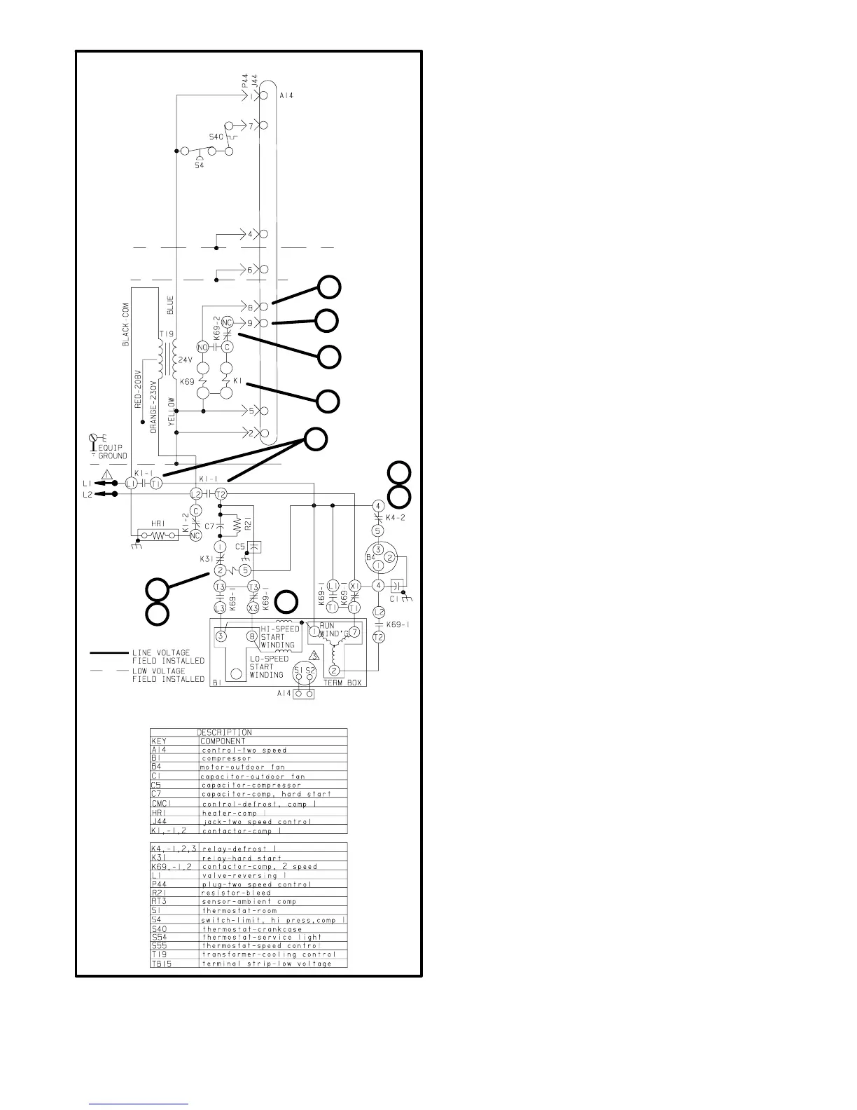
FIGURE 29
6
2
4
3
5
1
7
8
9
10
D−SINGLE-PHASE COMPRESSOR STARTUP
LOW SPEED
1− 1st stage demand: If all safety circuits check out, TSC energizes
JP44-9.
2− Contactor K1 is energized through K69-2 N.C. contacts. K1-2 contacts
open to de−energize the crankcase heater. All other K1 contacts close
to start outdoor fan operation and to begin compressor low speed start-
up.
3− Compressor B1 terminal 1 and the outdoor fan circuit are energized by
K1 contacts L1-T1. Compressor terminal 7 is energized by contactor
K1 terminal L2-T2 through contactor K69 terminal T1-X1. Compressor
terminal 8 (start winding) is energized by contactor K1 terminal L2-T2
through the start (C7) and run (C5) capacitors and contactor K69 termi-
nal T3-X3.
4− Outdoor fan B4 is energized through relay K4-2 when contactor K1
contacts L1-T1 and L2-T2 close.
5− As the compressor nears full speed, potential relay K31 energizes and
K31 contacts open to de-energize the start capacitor.
HIGH SPEED
6− 2nd stage demand: If all safety circuits check out, TSC energizes
JP44-8.
7− Contactor K69 energizes and K69-2 auxiliary contacts close to ener-
gize contactor K1. K1-2 auxiliary contacts open to de-energize the
crankcase heater. All other K1 contacts close. K1 contacts L1-T1,
L2-T2 and L3-T3 close while contacts T1-X1 and T3-X3 open.
8− Compressor B1 terminal 3 (start winding) is energized by contactor K1
terminal L2-T2 through the start (C7) and the run (C5) capacitors and
through contactor K69 terminal L3-T3. Compressor terminal 2 is ener-
gized by contactor K1 terminal L2-T2. Compressor terminal 1 is
energized directly by contactor K1 terminal L1-T1. Compressor termi-
nal 7 is energized by contactor K1 terminal L1-T1 through contactor
K69 terminal L1-T1.
9− Outdoor fan B4 is energized through relay K4-2 when contactor K1
contacts L1-T1 and L2-T2 close.
10− As the compressor nears full speed, potential relay K31 energizes and
K31 contacts open to de-energize start capacitor C7.