Page 5
I − UNIT INFORMATION
ELECTROSTATIC DISCHARGE (ESD)
Precautions and Procedures
CAUTION
Electrostatic discharge can affect electronic
components. Take precautions during unit instal-
lation and service to protect the unit’s electronic
controls. Precautions will help to avoid control
exposure to electrostatic discharge by putting
the unit, the control and the technician at the
same electrostatic potential. Neutralize electro-
static charge by touching hand and all tools on an
unpainted unit surface before performing any
service procedure.
All major components (indoor blower and coil) must be
matched according to Lennox recommendations for the
compressor to be covered under warranty. Refer to the En-
gineering Handbook for approved system matchups. A
missapplied system will cause erratic operation and can re-
sult in early compressor failure.
IMPORTANT
This unit must be matched with an indoor coil as
specified in Lennox’ Engineering Handbook.
II − UNIT COMPONENTS
Unit components are illustrated in figure 1.
COMPRESSOR
CHECK/EXPANSION
VALVE
CONTROL
BOX
REVERSING
VALVE
OUTDOOR
FAN/MOTOR
HPXA12 UNIT COMPONENTS
FIGURE 1
BI-FLOW
FILTER DRIER
SUCTION
MUFFLER
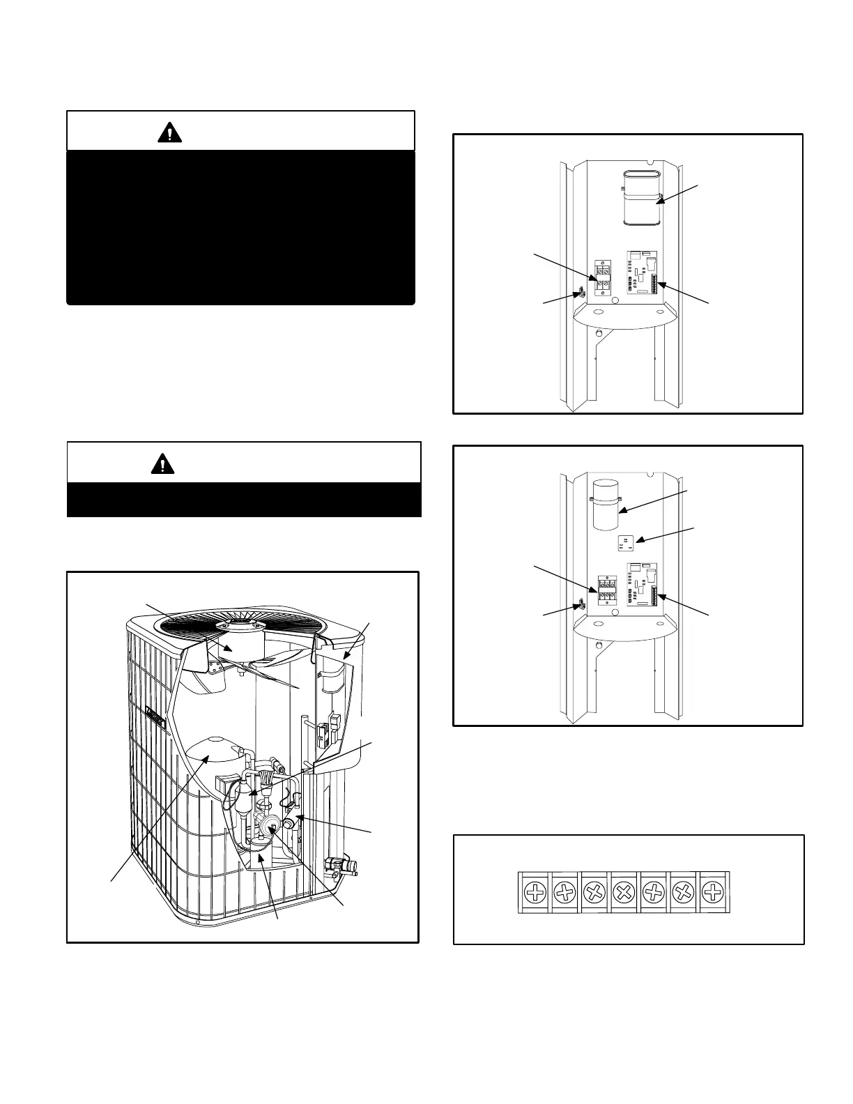
A − Control Box (Figures 2 and 3)
HPXA12 units are not equipped with a 24V transformer. All
24 VAC controls are powered by the indoor unit. Refer to
wiring diagram.
FIGURE 2
DUAL CAPACITOR
(C12)
COMPRESSOR
CONTACTOR
(K1)
SINGLE PHASE UNIT CONTROL BOX
GROUNDING
LUG
DEFROST
CONTROL
(A108)
FIGURE 3
RUN CAPACITOR
(C1)
COMPRESSOR
CONTACTOR
(K1)
THREE PHASE UNIT CONTROL BOX
GROUNDING
LUG
DEFROST
CONTROL
(A108)
OUTDOOR FAN
RELAY (K10)
460 VOLTAGE
ONLY
Electrical openings are provided under the control box cov-
er. Field thermostat wiring is made to a 24V terminal strip
located on the defrost control board located in the control
box. See figure 4.
CRW1OY1L
24V THERMOSTAT TERMINAL STRIP
FIGURE 4
Y2
 Loading...

