6
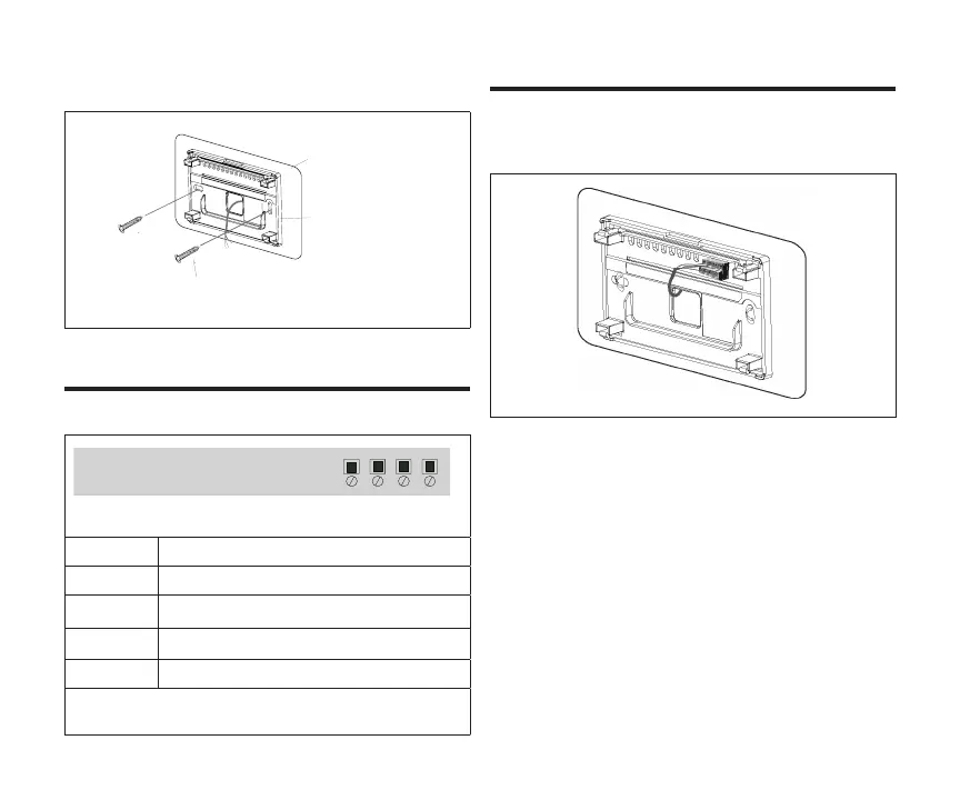
10. Secure back plate and wall plate (optional) to
wall with the two provided mounting screws.
Wall Plate (optional)
Zone Sensor Back Plate
Screw
Table 2. Terminal Designations
Terminal Purpose
PWR Zone sensor power 12VDC input.
D+ Zone sensor data high.
D- Zone sensor data low.
C Zone sensor 12VDC return.
See “Figure 2. Connecting Zone Sensor to Damper
Control Module” on page 7.
Use “Table 2. Terminal Designations” on page 6
for connecting the thermostat wiring to the back
plate terminals.
Figure 1. Backplate
NOTE: Remember to seal the hole in the wall with
a suitable material to prevent drafts from
entering the zone sensor case. Not doing
so could aect the zone sensor’s internal
temperature and humidity sensors.
NOTE: Use 2-pair, 18AWG unshielded thermostat
cable (eld-provided) for power terminals
(PWR and C). Recommend using 2-pair
22AWG shielded thermostat cable for
communications terminals (D+ and D-) which
will help eliminate any noise interference.

 Loading...