Page 21
Primary limit S10 is wired to the ignition control A3. Its N.C.
contacts open to de-energize the ignition control when ex
cessive temperature is reached in the blower compart
ment. If the limit trips, the blower relay coil K3 will be ener
gized by ignition control A3. Three limits with different
actuating temperatures are used for limits S10. Use appro
priate limit when replacement is required.
4-Flame Rollout Limit Switch S47
Flame rollout limit switch S47 is a SPST N.C. high-temper
ature limit located just above the burner air intake opening in
the burner enclosures (see figure 11 ). S47 is wired to the igni
tion control A3. When S47 senses flame rollout (indicating
a blockage in the combustion air passages), the flame
rollout limit trips and the ignition control immediately
closes the gas valve.
Limit S47 is factory-set to open at 290_F +
12_F (143_C +
6.7_C) on a temperature rise on all units. All flame rollout lim
its are manual reset.
5-Combustion Air Prove Switch S18
Prove switch S18 is a SPST N.O. switch located to the right
of the induced draft assembly. S18 monitors combustion air
inducer operation. Switch S18 is wired to the ignition control
A3. The switch closes on a negative pressure fall. This neg
ative pressure fall and switch actuation allows the ignition
sequence to continue (proves, by closing, that the combus
tion air inducer is operating before allowing the gas valve to
open.) The combustion air prove switch is factory-set and is
not adjustable. The switch will automatically open on a
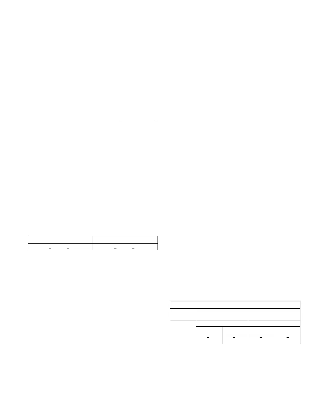
pressure rise (less negative pressure). Table 2 shows
prove switch settings.
TABLE 2
S18 Prove Switch Settings
Close“ w.c. (Pa) Open “ w.c. (Pa)
0.25 + 5 (62.3 + 12.4) 0.10 + 5 (24.8 + 12.4)
6-Combustion Air Inducer B6
Combustion air inducers on KGA092/150 units provide air
to the corresponding burners while clearing the combustion
chamber of exhaust gases. The inducer begins operating
immediately upon receiving a thermostat demand and is
de-energized when thermostat demand is satisfied.
The inducer uses a 208/230V single‐phase PSC motor
and a 4.81in. x 1.25in. (122mm x 32mm) blower wheel. All
motors operate at 3200RPM and are equipped with auto‐
reset overload protection. Inducers are supplied by vari
ous manufacturers. Ratings may vary by manufacturer.
Specific inducer electrical ratings can be found on the unit
rating plate.
On a heating demand (W1), the ignition control A3 initiates
the heating cycle. A3 then allows 30 seconds for the com
bustion air inducer to vent exhaust gases from the burners.
When the combustion air inducer is purging the exhaust
gases, the combustion air prove switch closes, proving that
the combustion air inducer is operating before allowing the
ignition sequence to continue. When the combustion air
prove switch is closed and the delay is over, the ignition
control activates the first-stage operator of the gas valve
(low fire), the spark and the flame sensing electrode.
Sparking stops immediately after flame is sensed or at the
end of the eight-second trial for ignition.
All combustion air inducer motors are sealed and cannot
be oiled. The inducer is not adjustable; but, it can be dis
assembled for cleaning.
7-Combustion Air Motor Capacitor C3
The combustion air inducer motors in all KGA units re
quire run capacitors. Capacitor C3 is connected to com
bustion air inducer B6. Ratings will be on the side of
capacitor or combustion air motor nameplate.
8-Gas Valves GV1
Gas valve GV1 is a two‐stage redundant valve. Units are
equipped with valves manufactured by White-Rodgers or
Honeywell. On a call for first-stage heat (low fire), the valve is
energized by the ignition control simultaneously with the spark
electrode. On a call for second-stage heat (high fire), the sec
ond-stage operator is energized directly from A3. A manual
shut-off knob is provided on the valve for shutoff. The man
ual shut‐off knob immediately closes both stages without
delay. On both valves, the first stage (low fire) is quick-opening
(on and off in less than 3 seconds).
On the White-Rodgers valve, the second stage is slow-open
ing (on to high fire pressure in 40 seconds and off to low fire
pressure in 30 seconds). The White-Rodgers valve is ad
justable for high fire only. Low fire is not adjustable. On the
Honeywell valve, the second stage is quick-opening. The
Honeywell valve is adjustable for both low fire and high
fire. Figures 17 and 18 show gas valve components. Table
3 shows factory gas valve regulation for KGA series units.
TABLE 3
GAS VALVE REGULATION
Max. Inlet
Pressure
Operating Manifold Pressure
13.0” W.C.
Natural L.P.
Low High Low High
1.6 + 0.2”
W.C.
3.7 + 0.3”
W.C.
6.5” + 0.3”
W.C
10.5” + 0.5”
W.C.
 Loading...
