Page 25
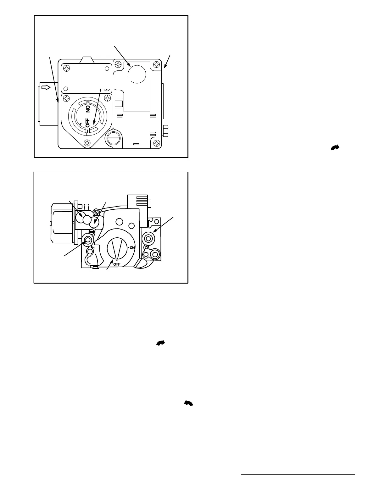
FIGURE 17
WHITE RODGERS 36C76 GAS VALVE
D-1
GV-1
C-1
C2
GV-2
GAS VALVE SHOWN
IN “OFF” POSITION
MANIFOLD
PRESSURE
TAP (SIDE)
HIGH FIRE MANIFOLD PRESSURE
ADJUSTMENT SCREW UNDER CAP
INLET
PRESSURE
TAP (SIDE)
HONEYWELL VR8205Q/VR8305Q SERIES GAS VALVE
Gas valve knob is shown in OFF position.
FIGURE 18
LOW FIRE
ADJUSTMENT
HIGH FIRE
ADJUSTMENT
INLET
PRESSURE
TAP
MANIFOLD
PRESSURE
TAP
3- This appliance is equipped with an ignition device
which automatically lights the burner. Do not try to light
the burner by hand.
4- Open or remove the heat section access panel.
5- Turn the knob on the gas valve clockwise
to “OFF”.
Push in 36C knob slightly. Do not force.
6- Wait five (5) minutes to clear out any gas. If you then
smell gas, STOP! Immediately call your gas suppli
er from a neighbor's phone. Follow the gas supplier's
instructions. If you do not smell gas, go to the next step.
7- Turn the knob on the gas valve counterclockwise
to “ON”. Do not force.
8- Close or replace the heat section access panel.
9- Turn on all electrical power to appliance.
10- Set thermostat to desired setting.
11- The combustion air inducer will start. The burners will
light within 40 seconds.
12- If the appliance does not light the first time (gas line
not fully purged), it will attempt up to two more ignitions
before locking out.
13- If lockout occurs, repeat steps 1 through 10.
14- If the appliance will not operate, follow the instructions
“Turning Off Gas to Appliance” and call your service
technician or gas supplier.
Turning Off Gas to Unit
1- If using an electromechanical thermostat, set to the
lowest setting.
2- Before performing any service, turn off all electrical
power to the appliance.
3- Open or remove the heat section access panel.
4- Turn the knob on the gas valve clockwise
to “OFF”.
Push in 36C knob slightly. Do not force.
5- Close or replace the heat section access panel.
C-Cooling Startup
1- Initiate first- and second-stage cooling demands ac
cording to instructions provided with thermostat.
2- First-stage thermostat demand will energize compres
sor 1. Second-stage thermostat demand will energize
compressor 2. On units with an economizer, when out
door air is acceptable, a first-stage demand will ener
gize the economizer; a second-stage demand will en
ergize compressor 1.
3- Units contain two refrigerant circuits or stages. See fig
ure 19.
4- Each refrigerant circuit is separately charged with re
frigerant. See unit rating plate for correct amount of
charge.
NOTE - Refer to IV-CHARGING for proper method to check
refrigerant charge.
Three-Phase Scroll Compressor Voltage Phasing
Three-phase power supplied to the unit disconnect
switch must be phased sequentially to ensure the scroll
compressor and indoor blower rotate in the correct direc
tion. Compressor and blower are wired in phase at the
factory. Power wires are color-coded as follows: line
1-red, line 2-yellow, line 3-blue.
1- Observe suction and discharge pressures and blower
rotation on unit start-up.
2- Suction pressure must drop, discharge pressure must
rise and blower rotation must match rotation marking.
If pressure differential is not observed or blower rotation is
not correct:
3- Disconnect all remote electrical power supplies.
4- Reverse any two field-installed wires connected to the
line side of K2 contactor or disconnect switch if in
stalled. Do not reverse wires at blower contactor.
 Loading...
